Exhaust fans typically have a gravity damper within the wall vent or a butterfly damper within the exhaust duct. The purpose of these backdraft dampers is to prevent outdoor air from making its way back into the house. The dampers only allow air to flow from the bathroom to the outside in one direction. During windy days when large gusts of wind blow against the building, the backdraft damper prevents the air from entering.
The problem with these types of backdraft dampers is that most of them are not airtight. This results in a continuous exchange of either cold or warm air entering or exiting the building depending on the climate. This can be uncomfortable, and it is not energy efficient. Additionally, these types of dampers are prone to mechanical failure where the return spring eventually breaks. This article will discuss two alternative methods to the traditional exhaust fan backdraft damper.
Method 1:
Install a 3 wire damper in an exhaust duct
Safety Note
Before proceeding with any wiring, use a multi-meter and set it to VAC. Measure the voltage across the source circuit wiring in the exhaust fan switch or timer wall electrical box. Then turn off the supply breaker to this electrical circuit located in your homes electrical panel. Then go back and measure the voltage across the source circuit again, it should now be zero volts. When multiple people reside within the building, lock out the circuit breaker using LOTO to ensure it remains off. For safety reasons, never work on electrical equipment while it is live. Additionally, this installation may require an electrical permit before starting work. Check with your local jurisdiction and be sure to follow all local electrical codes.

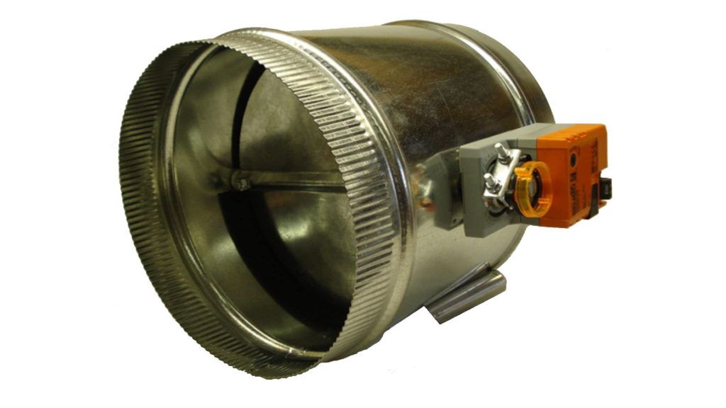
3 Wire Damper
- Power open & power close (3 Wire) 24VAC, 2.5VA
- Run time: 60 Second (90 Deg)
- Torque: 45 in-lbs
- Full-seal gasket blade.
Parts Required
- 3 wire damper actuator
- 18/3 thermostat wire
- Cable glands
- 14/3 electrical wire
- Electrical cable connector
- Electrical cable connector bushing
- Junction box
- 120/24V transformer
- Control relay
- Wire nuts
Warning!
If you are uncomfortable or do not completely understand the equipment or how to wire it, it is best to hire a professional for help. Wiring this equipment incorrectly may cause damage.
How the 3 wire damper behaves like a backdraft damper
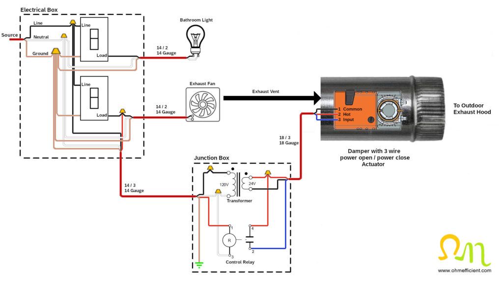
This circuit integrates a 3 wire power open, power close actuator that controls the position of the damper within the duct. When the exhaust fan is off, the damper assembly should be in the closed position. The black and white wires on the primary side of the transformer must connect to the source circuit within the electrical box. This allows the transformer to continuously supply 24VAC to the hot and common terminals of the actuator. When the exhaust fan switch is turned on, 120VAC is applied to the red wire of the 14/3 cable. This applies 120VAC across the control relay coil which closes the contact between terminals 2 and 4. When this contact closes, 24VAC is applied to the input terminal of the actuator. Applying 24VAC to the input terminal of the actuator opens the damper and allows exhaust air to flow outside.
Note
When the exhaust fan is off and only the hot and common terminals are receiving 24VAC, the damper should be closed. If it is not, simply toggle the actuators reversing switch located on the cover of the actuator.
3 wire damper on/off control operation
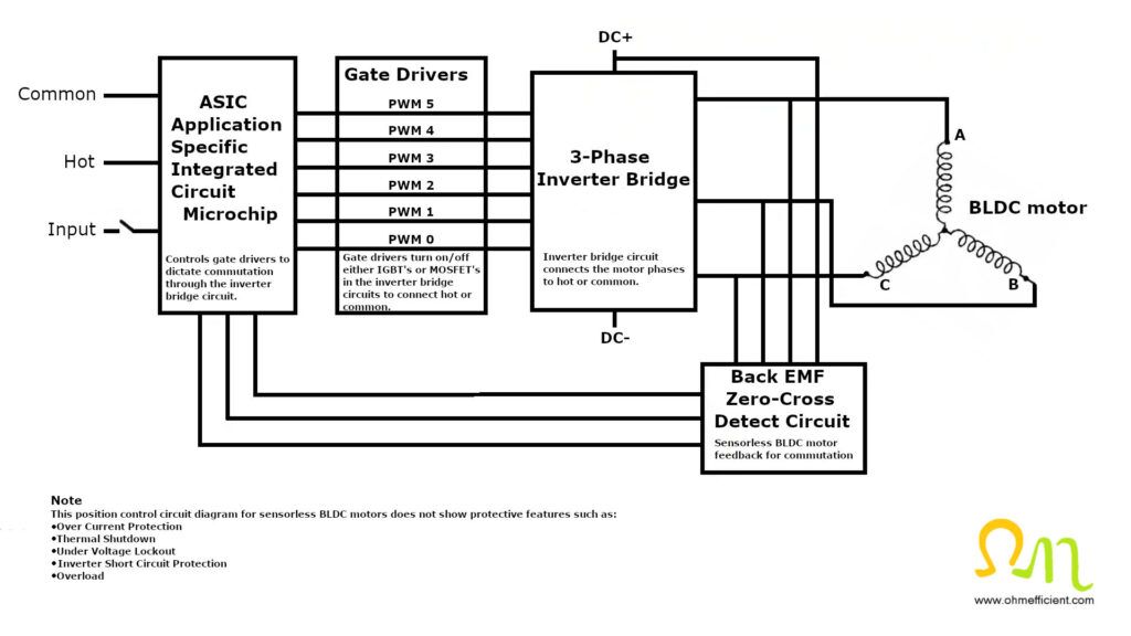
The actuator uses a sensorless brushless DC (BLDC) motor that is controlled by an Application Specific Integrated Circuit (ASIC) microchip. The actuator opens or closes the damper based on the state of the input terminal. When the input terminal receives 24VAC, the actuator opens and consumers approximately 1.5 watts of power for 90 seconds. Once the actuator reaches the fully open position, the power consumption reduces to approximately 0.2 watts in the rest position. Switching the exhaust fan switch off or when the timers time elapses, the control relay’s coil drops out. The control relay contact opens and removes the 24VAC to the actuator’s input terminal. The actuator closes and again consumes approximately 1.5 watts of power for 90 seconds. Once the actuator reaches the fully closed position, the power consumption reduces to approximately 0.2 watts in the rest position.
This control operation is considered on/off control, where the actuator will be either fully open or fully closed at rest position. The 3 wire power open, power closed damper actuator assembly includes foam gasketing between the duct and the damper blade. This gasket provides a better seal as the damper blade is preset to rotate and firmly seal against the gasketing.

Method 2:
Installing a cape backdraft damper in an exhaust duct
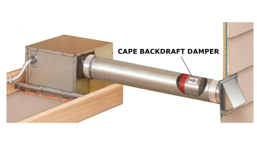
The cape backdraft damper uses a fabric sleeve that opens when an exhaust fan is in operation and then collapses in on itself when the airflow stops. The collapsed fabric sleeve prevents airflow in the opposite direction, creating an airtight seal. The cape backdraft damper’s airtight seal is more efficient than traditional gravity and butterfly dampers.
The installation of a cape backdraft damper is easy. Simply disconnect a piece of exhaust duct from the fan near the wall outlet and insert the damper. The damper includes an open cell gasket on its outer edge which ensures a tight fit within the duct.

Cape Backdraft Damper
The Cape backdraft damper opens and closes with minimal airflow in either direction, preventing cold air from coming in and making the home more comfortable and energy efficient.
Parts Required
Pros:
- Easy do it yourself installation
- Economical
- More efficient than traditional gravity or butterfly backdraft dampers
Cons:
- Must be installed in a horizontal position, whereas the motorized damper method can be installed vertically, if required.
- Cold climates may experience freezing or ice buildup on the fabric sleeve.
Backdraft damper leakage and efficiency
Most gravity or butterfly backdraft dampers are not airtight, even when their blades are fully closed. Air that flows through the closed damper is referred to ‘leakage’. Leakage airflow results in temperature loss to the outside environment. This will lead to uncomfortable drafts and energy waste. A 3 wire damper ensures the damper only opens when the exhaust fan is running, and has minimal leakage compared to traditional backdraft dampers. Additionally, both powered and cape style backdraft dampers greatly reduce the chance of a stuck damper.
Related articles


