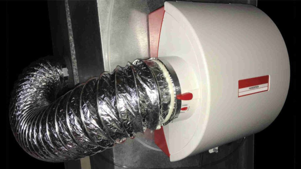
A Nest thermostat can also function as a humidistat to control your home’s relative humidity. This article includes drawings and electrical wiring diagrams explaining how to set up and wire a Nest thermostat, humidifier and furnace. The benefits of controlling your home’s relative humidity relating to comfort and energy savings will also be reviewed.
Buildings in cold climates require additional humidity
As the seasons change from summer to fall (autumn) to winter, the outdoor air temperature changes from warm to cold. Water vapor molecules in the warm summer air are in a gaseous state that is fast moving and spread apart from each other. As the outdoor temperature cools, the water vapor molecules slow down and become closer. Consequently, this can change the state of the water vapor molecules from a gas to a liquid. When the air comes in contact with cool surfaces, the water vapor molecules will condense onto the cool surface. Hence, condensation reduces the water vapor molecules present in cold air. When heating this cool low water vapor air without additional humidification, the water vapor content remains the same. As a result, the air’s relative humidity decreases.
Relative Humidity is defined as the percentage of water vapor present in the air, in relation to the amount needed for saturation at any given temperature. Heating cold air with low water vapor to a higher temperature allows for the air to take on more water vapor. Therefore, the warm air will now take moisture from wherever possible via the evaporation process. The air will evaporate water vapor from items like hardwood floors and furniture. Additionally, the air will evaporate water vapor from the human body.
How the human body reacts to relative humidity
(why you may feel cold even when the room temperature is 70oF / 21oC)
The human body is continuously generating heat. Displacing this heat occurs from a combination of conduction, convection and evaporation processes. Conduction is a heat transfer that is proportional to the differential temperature of the human body and another object. Convection is a heat transfer via movement of air across the skin. Evaporation is a heat transfer from the conversion of a liquid to a gas.
Relative humidity affects the human body’s ability to displace heat via the evaporation process. To emphasize this, let’s look at two extreme examples of heat displacement from the evaporation process. When the relative humidity is 0%, the air is very dry and evaporates moisture from the human body easily. This evaporation process cools down the human body. When the relative humidity is 100%, the air is completely saturated and zero moisture evaporates from the human body. If the human body has no other heat transfer processes occurring, overheating will occur.
Heat index
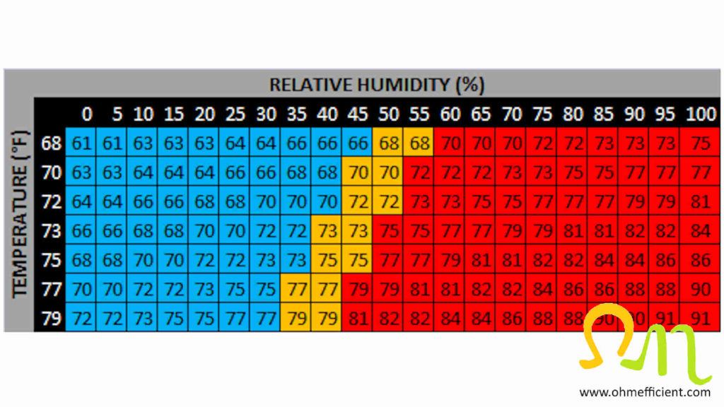
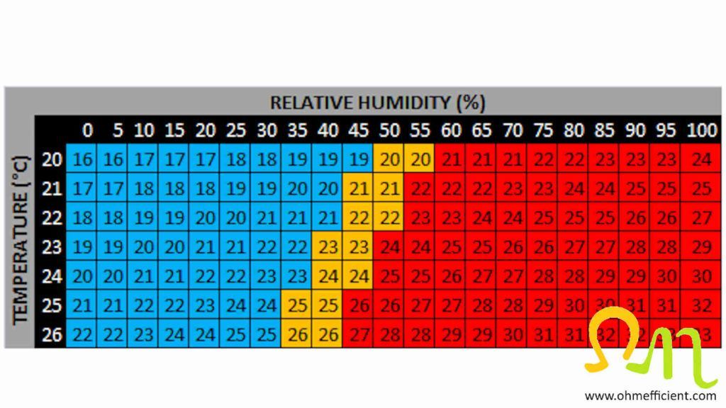
The heat index is a concept that refers to how cold or hot the human body feels at different temperatures and relative humidity levels. Refer to the heat index tables below: everything in blue feels cooler to the human body compared to the actual temperature. Everything in orange feels like the actual temperature. Everything in red feels warmer to the human body compared to the actual temperature.
Example
Air heated to 70oF will feel like 70oF when the relative humidity level is between 45 and 50%. However, if the relative humidity in the building is 15%, the air will feel like 64oF. When the relative humidity is 15%, increasing the thermostat setting 5oF to a setting of 75oF, will make the air feel like 70oF again.
Humidifiers require warm air during operation
A flow-through humidifier uses water that drips onto a pad which evaporates while the furnace is running and warm air passes through it. If there is excess water that does not evaporate during the heating cycle, the water flows out a drain line. A saddle valve connected to the homes water line connects to the humidifier solenoid valve via tubing. When the Nest thermostat calls for heat and humidity, a voltage is applied to the humidifiers solenoid valve. Applying voltage across the solenoid valve, opens the valve allowing water to flow through. Closing the saddle valve a little prevents too much water from flowing down the drain line. The saddle valve does however need to be open enough to maintain the desired humidity levels.
Minimal evaporation takes place when these humidifiers operate with only the furnace fan running. These humidifiers require warm air to flow through them for proper evaporation to take place. Operating these humidifiers without warm air, essentially opens the solenoid valve and pours water down the drain the entire time the fan is running. Refer to “How to set up the Nest Thermostat relative humidity settings” section below in order to ensure this is set up correctly.
Bypass flow through humidifier
A bypass flow-through humidifier typically installs on the cold air return ductwork. A round 6-inch flexible duct connects the supply air ductwork to the side of the humidifier. This allows for a small portion of warm air to bypass the supply ductwork which then supplies the humidifier with warm air required for evaporation. During the winter season, the damper blade on the bypass duct (or on the humidifier housing) should be open to allow for warm air to bypass through the humidifier. During the summer season, closing the damper blade on the bypass duct, prevents cool air from flowing through humidifier. Additionally, closing the damper blade increases air conditioning efficiency as cool air does not need to repeatedly cycle through the air conditioner evaporator coil.
AprilAire 500M Whole-House Humidifier
This humidifier was designed and manufactured in the USA by AprilAire – the inventor of the whole home evaporative humidifier, and the leader in indoor air quality solutions.
Note
The red numbers in the bypass humidifier picture below illustrates the wiring connections in the humidifier wiring diagram.
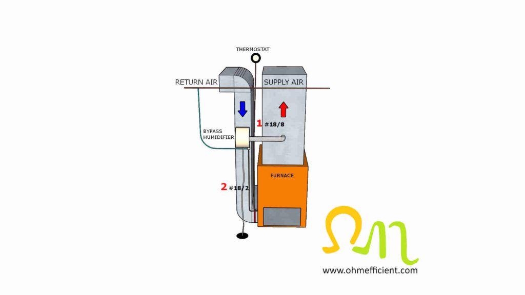
If you plan on installing a bypass flow through humidifier, read the instruction manual before proceeding. If you intend to use a Nest thermostat to control humidity, refer to the wiring diagram shown in the “Wire Nest Thermostat to humidifier” section below.
Powered flow through humidifier
A powered flow-through humidifier needs to be installed above the furnace on the supply side of the forced air ductwork. A powered flow through humidifier does not have a 6” bypass flexible duct connecting the supply and return ducts. Instead, it has a fan that turns on at the same time the solenoid valve opens. The fan draws warm air from the supply duct through the humidifier pad and returns it back to the supply duct. This type of humidifier is also an evaporation type humidifier and requires warm air to operate effectively.
AprilAire 700M Whole-House Humidifier
AprilAire Humidifiers can help you maintain optimal humidity in your home of 40% – 60% so you’ll feel more comfortable while also preserving items in your home susceptible to damage from changing humidity or dry conditions.
Note
The red numbers in the powered humidifier picture below illustrates the wiring connections in the powered humidifier wiring diagram. The powered humidifier will also need to plug into a 120V outlet.
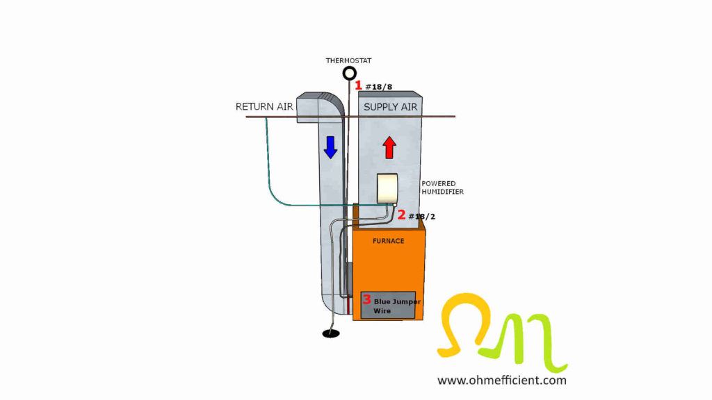
If you plan on installing a powered flow through humidifier, read the instruction manual before proceeding. If you intend to use a Nest thermostat to control humidity, refer to the wiring diagram shown in the “Wire Nest Thermostat to powered humidifier” section below.
Nest Learning Thermostat
Nest’s smartest, most advanced thermostat yet, the Nest Learning Thermostat (4th gen) is a beautiful, brilliant way to save energy, keep your home comfortable, and help make sure your heating and cooling systems are running smoothly.
Safety note
Before proceeding with any wiring modifications, use a multi-meter and set it to VAC. Measure the voltage across the R and C terminals on the furnace terminal board. It should be approximately 24VAC. (Most furnaces have an interlock switch that opens when you access this area of the furnace. Momentarily press in on this switch to measure the 24VAC). Then either turn off the supply breaker to the furnace located in the electrical panel, or turn off the maintenance switch located near the furnace. To be sure, no voltage remains, go back and measure the voltage across the R and C terminal. At this point, there should now be zero volts with the interlock switch is in either position. For safety reasons, never work on electrical equipment while it is live.
Thermostat Wire 18/8
50 feet of premium, CL2/R CMR Rated Brown thermostat wire 18/8. Thermostat cable is made from pure copper, and features solid 18 gauge copper conductors with a sunlight resistant outer jacket.
Tools and equipment required
- Nest Learning Thermostat
- Bypass Flow Through Humidifier (homes up to 3500 Sq. Ft.)
- Replacement Humidifier Pads
- 18/8 Thermostat Wire
- Multi-Meter
- Wire Stripper
- Sheet Metal Snips
- Adjustable Wrench
- Level
- Cut Resistant Safety Gloves
Warning!
If you are uncomfortable or do not completely understand the equipment or how to wire it, it is best to hire a professional for help. Wiring this equipment incorrectly may cause damage.
Bypass flow through humidifier operation
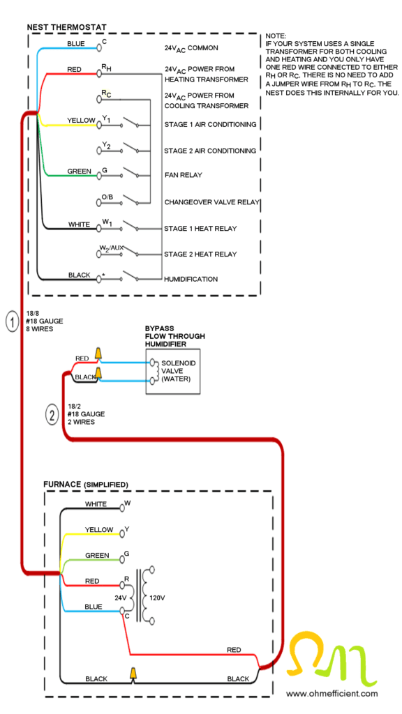
The bypass flow through humidifier will come with a sail switch or pressure switch, a humidistat as well as a 120/24V plug-in transformer. You will not need any of these items when using the Nest thermostat to control humidity. Sail or pressure switches detect air movement within the ductwork. These switches are electrically wired in series with a humidistat to prevent humidifier operation when the furnace is not running. The Nest thermostat has a setting that requires both heat and humidity before it activates the humidifier. These switches are therefore no longer required. They would just be redundant mechanical switches that will eventually fail, resulting in troubleshooting humidifier electrical circuits. Do NOT use the 120/24V plug-in transformer. The 24VAC required to open the humidifiers solenoid valve comes from the transformer connected to terminals R and C within the furnace.
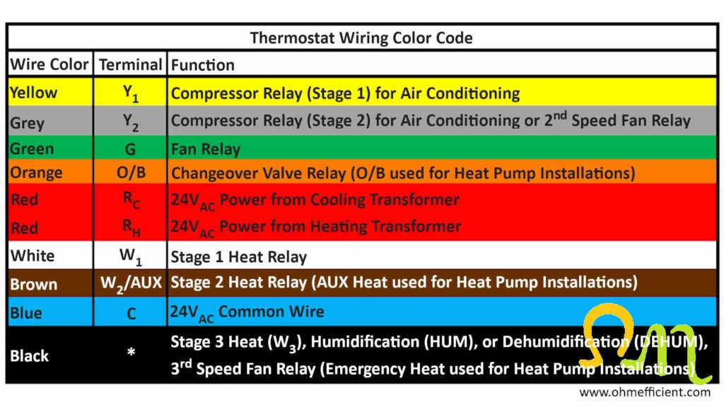
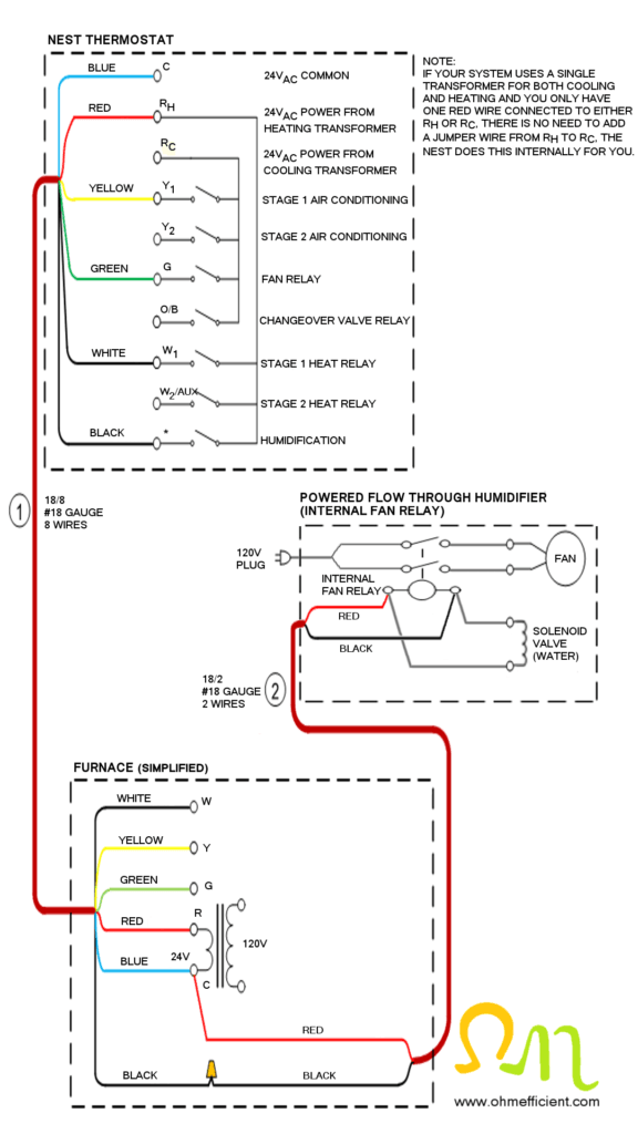
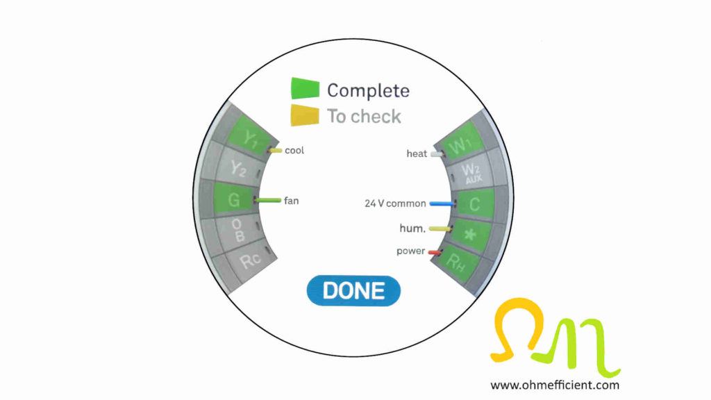
The thermostat black wire connecting to the Nest’s * connector, controls the operation of the humidifier. A wire nut connects the black of the 18/8 thermostat wire to the black of the 18/2 thermostat wire within the furnace. The red of the 18/2 thermostat wire connects to the 24VAC common C terminal on the furnace terminal board. When there is a call for heat and humidity, the Nest will close its * “switch” and apply 24VAC to the humidifier solenoid. Once a voltage applies across the solenoid valve, the valve opens allowing water to flow through which provides additional humidity.
Wire Nest Thermostat to powered humidifier
Safety note
Before proceeding with any wiring modifications, use a multi-meter and set it to VAC. Measure the voltage across the R and C terminals on the furnace terminal board. It should be approximately 24VAC. (Most furnaces have an interlock switch that opens when you access this area of the furnace. Momentarily press in on this switch to measure the 24VAC ). Then either turn off the supply breaker to the furnace located in the electrical panel, or turn off the maintenance switch located near the furnace. To be sure, no voltage remains, go back and measure the voltage across the R and C terminal. At this point, there should now be zero volts with the interlock switch is in either position. For safety reasons, never work on electrical equipment while it is live.
Control Relay
General purpose relay with a 24V coil. Suitable for switching circuits in various heating, ventilation, and air conditioning systems. It has four spade terminals for quick, reliable connections for single pole normally open switching capabilities.
Tools and equipment required
- Nest Learning Thermostat
- Powered Flow Through Humidifier (homes up to 4500 Sq. Ft.)
- Replacement Humidifier Pads
- Control Relay (required when isolating two 24VAC sources)
- Insulated Wire Crimps and Crimping Tool (required for control relay)
- 18/8 Thermostat Wire
- Multi-Meter
- Wire Stripper
- Sheet Metal Snips
- Adjustable Wrench
- Level
- Cut Resistant Safety Gloves
Warning!
If you are uncomfortable or do not completely understand the equipment or how to wire it, it is best to hire a professional for help. Wiring this equipment incorrectly may cause damage.
Powered flow through humidifier operation
The powered flow through humidifier will come with a sail or pressure switch as well as a humidistat. As mentioned previously, none of these items are required when using the Nest thermostat to control humidity.
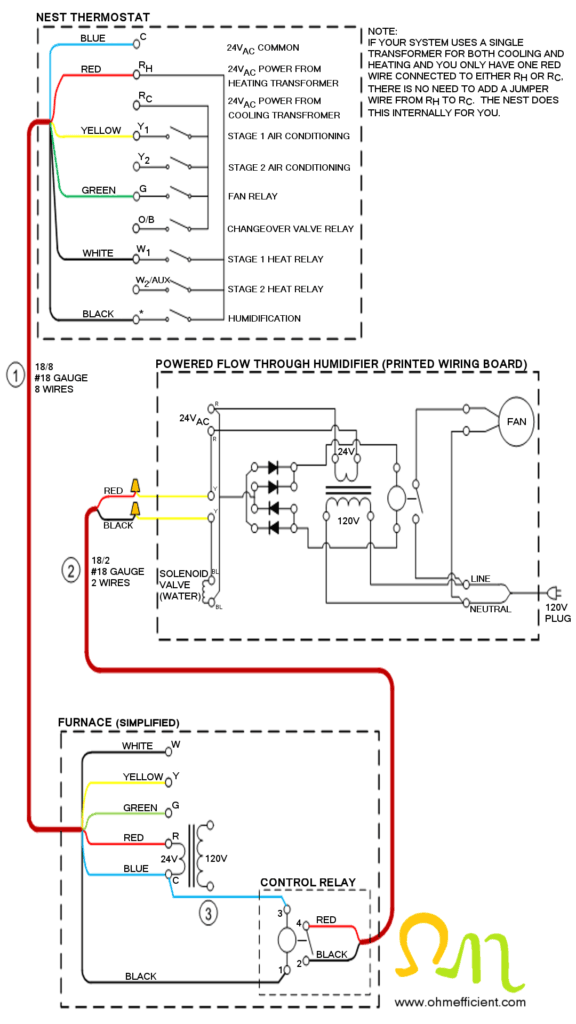
A Single Pole Normally Open (SPNO) relay is required for this humidifier application. The powered flow through humidifier has a 120V plug to supply power to operate its fan. The power for this is distributed internally via a printed wiring board. The printed wiring board also includes a 120/24V transformer that supplies the solenoid valve with voltage when a humidistat calls for it. The SPNO relay isolates these two 24VAC sources. If this relay is not used and the transformer in the furnace and the transformer in the humidifier are of different polarities (additive and subtractive) damage to the equipment will occur. Connecting transformers with opposite polarities in parallel results in large circulating currents that will damage equipment and possibly cause a fire.
The thermostat black wire connecting to the Nest’s * connector, controls the operation of the humidifier. The black of the 18/8 thermostat wire connects to terminal 1 of the relay mounted inside the furnace. A blue jumper wire connects terminal 3 of the relay to the 24VAC common C terminal within the furnace. The black and red of the 18/2 thermostat wire connects terminals 2 and 4 of the relay to the humidifier. When heat and humidity is called for, the Nest will close its * “switch” and apply 24VAC to the relay. The switch on the relay will then close. This applies 24VAC from the internal humidifier transformer to the solenoid valve and humidifier fan relay. This will open the water valve and turn on the humidifier fan to allow for humidification.
Update
Powered flow through humidifier with internal fan relay
Some newer powered flow through humidifiers use an internal fan relay instead of a printed wiring board. When the Nest thermostat calls for humidity, 24VAC is applied to the humidifiers internal fan relay coil as well as the solenoid valve coil. Applying 24VAC across the fan relay coil closes the relay contacts which then applies 120VAC to the fan from the extension cord that plugs into the wall. Applying 24VAC across the solenoid valve coil, opens the valve which allows water to flow through the water panel evaporator pad.
Wiring this type of humidifier is similar to wiring the bypass flow through humidifier. Since this style of humidifier does not incorporate an internal transformer, isolating 24VAC sources is not required.
Set up Nest Thermostat humidifier settings
The humidity settings on the Nest thermostat only show up once you have a wire connected to the * connection. The Nest will then try to maintain the relative humidity setting based on the current inside temperature setting.
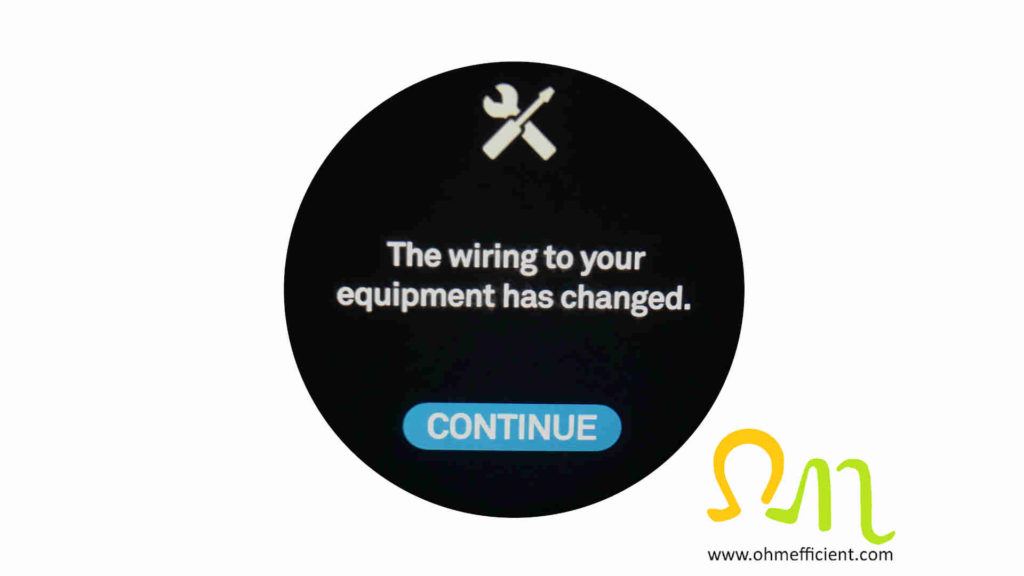
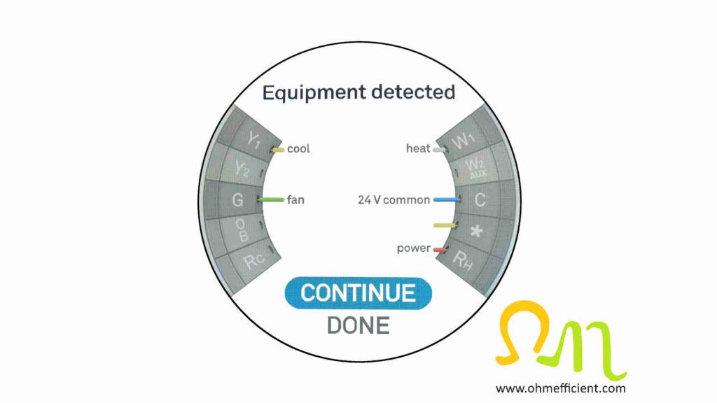
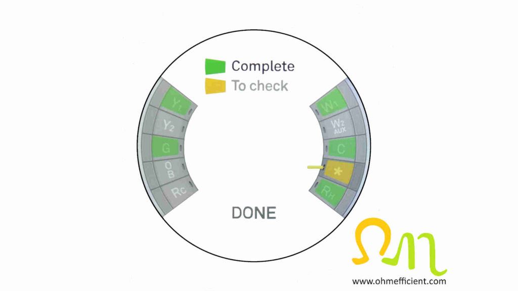
Notice the wire in the * connection is not labeled. This is because the * connection can be set up to be either stage 3 heat, humidification, dehumidification, 3rd speed fan relay, or emergency heat for heat pump applications. Select “CONTINUE”
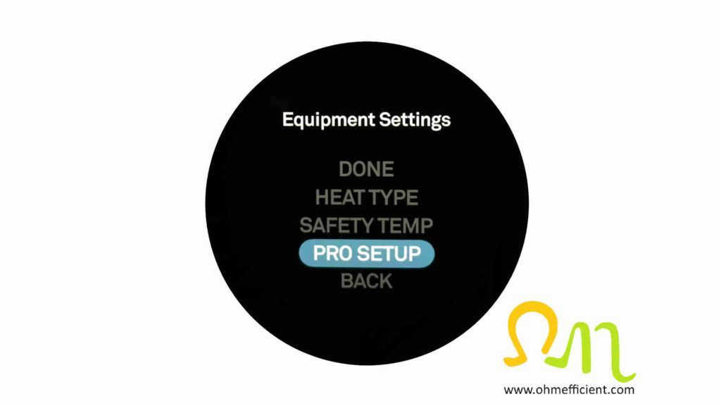
Select “PRO SETUP”
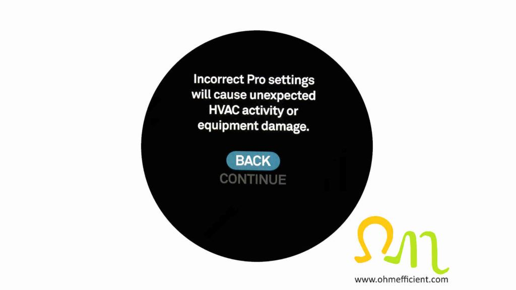
A statement then appears that states “Incorrect Pro settings will cause unexpected HVAC activity or equipment damage”. Turn and select “CONTINUE”
Turn to the * connection which is yellow (indicating that it needs to be checked) and then push on the Nest
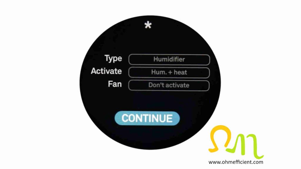
Select “Humidifier” for Type.
Select “Hum. + heat” for Activate. This is the setting that allows for the humidifiers solenoid valve to be opened only if heat is also called for. If you select “Hum. only”, the solenoid valve will be opened every time humidity is called, even without the required furnace heat.
Select “Don’t activate” for Fan. The humidifier will only be on during a heat call, therefore the fan will already be running.
The * connection is now complete. It now shows up as hum.
Go to Humidifier and select “SET HUMIDITY”
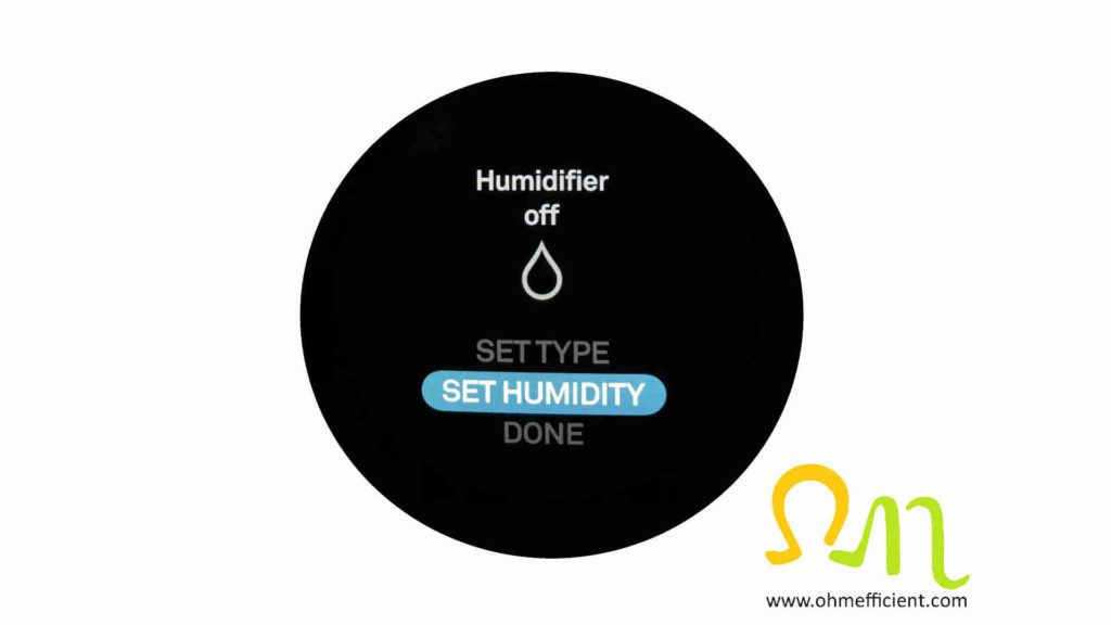
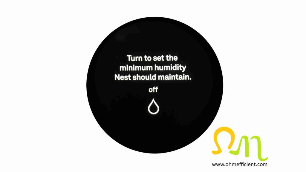
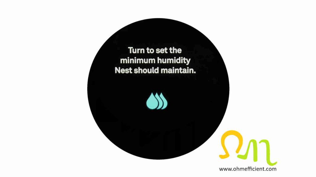
Turn to set the minimum humidity Nest should maintain. An empty drop indicates 0% relative humidity. Three fully shaded drops indicates 100% humidity.
Setting humidity from the Nest Thermostat App
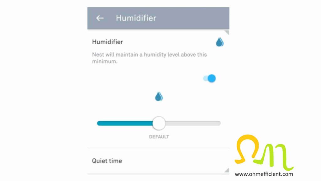
Note: the Nest App uses a scrollbar. Fully left is 0% relative humidity; fully right is 100% relative humidity.
Pro tip
Ensure you connect the Nest thermostat 24VAC common wire to the C connector of the thermostat. Everything will work without it, until the internal battery within the Nest thermostat fails. If you don’t connect this, hopefully you are home when the battery fails and not on vacation.
Energy savings from controlling relative humidity
Let’s look at the energy savings from the example in the “How the human body reacts to relative humidity” section above. In this example, you could decrease the temperature by 5oF / 3oC and still feel comfortable by controlling relative humidity. The U.S. Department of Energy’s Energy Saver Guide states, “You can save as much as 10% per year on heating and cooling by turning the thermostat down 7 to 10oF for 8 hours a day in the fall and winter; turn it up in the spring and summer” [1]. Referencing this Energy Savings Guide, we can then recalculate the energy savings for this example. As a result of decreasing the temperature by 5oF / 3oC 24 hours a day, an energy savings of 15% can be achieved.
Conclusion
Outdoor humidity levels are lower during the cold winter season. The relative humidity within a building decreases when air is heated without added humidification. As a result, this low relative humidity makes people uncomfortable by cooling their body temperature through the evaporation process. Comfort levels as well as energy savings will be achieved by controlling relative humidity.
After the humidifier is installed, use a humidity & temperature smart sensor to monitor and trend the homes comfort levels. Place the sensor anywhere throughout the home while using the smart phone app to view current and historical temperature and relative humidity levels.
Humidity & Temperature Smart Sensor
SensorPush is always monitoring and recording temperature, humidity, dew point, and VPD, ready to alert you when you’re in Bluetooth range, or even from afar with the G1 WiFi Gateway.
Related content
Duct Sealing Improves HVAC System Efficiency
How to set up a Nest Thermostat with a whole house dehumidifier
References
[1] U.S. Department of Energy 2017 Energy Saver Guide: Tips on Saving Money and Energy in Your Home (English) (available at https://www.energy.gov/energysaver/downloads/energy-saver-guide)

