
This article describes how HVAC duct sealing creates a more comfortable living environment while improving heating and cooling system efficiencies. Energy efficiencies increase by applying duct mastic to seal all forced air ductwork connections, seams, and joints. This includes all supply and return air ductwork internal or external to the building envelope. Fresh air supply ducts are intentional openings within the ductwork that bring fresh outdoor air into a building. Installing a motorized shut-off damper in line with the fresh air ductwork seals this opening when forced air systems are not in operation. Before and after photos as well as fresh air motorized shut-off damper wiring diagrams are included below.
Room Temperature Discomfort
Room air temperature naturally layers with cool dense air at floor level and less dense warm air at ceiling level. This layering effect known as “thermal stratification” is a major contributor to room discomfort.

Non-sealed supply and return ductwork creates improper airflow entering and exiting a room. This results in room air temperature that does not completely “de-stratify”. In cold climates, return air grilles are located at floor level. These grilles pull cool dense air out of a room and return it to the furnace for reheating. When these ducts have leaks, they pull a mixture of cool dense air from the room and warm ceiling air from the floor below. In hot climates, return air grilles are located near ceiling level. These grilles pull warm air out of a room and return it to the air conditioner for cooling. Similarly, leaks in these ducts pull a mixture of warm air from the room and cool air from floor level.
The mixing of air leaks within return air ductwork results in an inability to balance the room temperature from floor to ceiling. Consequently, the thermal stratification effect reestablishes in a short period, making the room uncomfortable.
Energy Consumption Resulting from Duct Leakage
Energy waste from non-sealed supply and return air ductwork occurs within buildings conditioned and unconditioned spaces.
Ductwork Leakage within a Buildings Envelope (Conditioned Space)
Leaks in return air ductwork wastes energy either reheating or cooling already conditioned air. Additionally, thermostats within buildings that quickly reestablish thermal stratification, continually cycle on an off in an ineffective effort to maintain a desired temperature. This results in the furnace or air conditioner cycling on and off more often. Continuously cycling the furnace or air conditioner on and off can lead to premature equipment failure. This could end up in additional costs in parts and labor for repairs.
Ductwork Leakage to Outside Building Envelopes (Unconditioned Spaces)
Depending on building construction and location, HVAC ductwork can be inside or outside a buildings envelope. Some HVAC ductwork installations are a combination of both. A buildings envelope refers to intentionally conditioned and unconditioned spaces within a building. For example, attics and crawlspaces are typically unconditioned spaces. Basements and garages can be either conditioned or unconditioned spaces depending on their purpose.
In cold climates, it is common to see ductwork within conditioned spaces. Exceptions to this include ductwork runs through unconditioned crawlspaces. In hot climates, it is common to see ductwork within attics that are not conditioned.
When non-sealed ductwork runs through unconditioned spaces, energy losses can be significant. Leaks in supply ducts running through an unconditioned attic in hot climates will supply cool air into the attic. Leaks in return ducts will pull some warm air from the attic rather than fully from the conditioned spaces. Likewise, non-sealed ducts in cold climates either pull cool air or supply warm air to unconditioned spaces. Leaks in ductwork within unconditioned spaces waste energy by unintentionally conditioning the space to a certain degree.
Additionally, it takes more energy conditioning air with a larger temperature difference between return air and desired room temperature. A furnace unintentionally returning air at 50oF from an unconditioned space will run longer then if it were fully returning 64oF from the conditioned space. Similarly, an air conditioner pulling higher temperature attic air needs to run longer than if it fully pulled return air form the conditioned spaces.
Applying Mastic Duct Sealant
- Clean dust and debris from the ductwork connections, seams, and joints to ensure the masitc adheres well to the ductwork.
- Use a brush or caulking gun to apply the UL181-rated mastic in a continuous coat approximately the thickness of a nickel. Applying the mastic to this thickness ensures an airtight seal, if the mastic starts to crack as it ages.
- Apply the mastic with a ½-inch overlap.
- Reinforce openings or gaps greater than 1/4-inch with mesh tape before applying mastic to the ductwork.
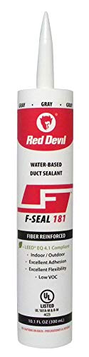
Duct Sealant/Mastic
High quality, fiber reinforced water based duct sealant/mastic that is UL 181 A-M & B-M and can be used on all types of HVAC ductwork.

Note
Use mesh tape to reinforce holes of this size before applying mastic.


Note
A major source of duct leakage occurs when floor joist cavities function as return air ductwork. Panned floor joists use either metal or corrugated sheets nailed to floor joists to create a return path. The negative return air pressure during HVAC system operation draws in air from leaks along the panned return. Panned ductwork returns have many sources of leakage including the following:
- Leaks between the flooring material and the floor joist
- Leaks between the panned sheet material and floor joist
- Panned joist end caps
- Electrical wring running through the panned floor joist
- Panned joist to rectangular sheet metal trunk ductwork connections

Note
Use expandable foam for duct sealing leaks created by electrical wiring running through panned floor joist returns.
Spray Foam Sealant
Polyurethane-based insulating foam sealant offers premium durability with its high density, flexibility, strong adhesion and UV resistance. It expands to fill, seal, and effectively insulate gaps and cracks up to 3 inches in size.


Fresh Air Damper Installation
Clean unconditioned outdoor air enters buildings through fresh air intakes. The purpose of the fresh air intake is to dilute contaminated or stale indoor air to improve indoor air quality. Depending on building construction, these fresh air intakes may connect to the return air ductwork. The fresh air mixes with the return air and proceeds through either the furnace of the air handler filter before conditioning and distribution into the building.
Fresh air intakes that directly connect return air ductwork outside is in effect a five or six inch non-sealed hole to the outdoors. Although fresh air is required for human occupancy, this has a negative effect on energy efficiency. In cold climates, cool dense outdoor air will work its way down the fresh air intake and settle inside the building.
Installing a sealed fresh air shut-off damper within the fresh air ductwork can solve this issue. The motorized damper closes against foam seals when either the air handler or furnace are not in operation. The damper opens to allow fresh air intake during the conditioning of air form either the furnace or the air handler. Incorporating an override switch within the motorized damper wiring allows for manual opening of the fresh air damper whenever required.
Fresh Air Damper Operation
Determining when fresh air dampers should open or close depends on building size, number of occupants, and the natural air infiltration of the building. Opening the fresh air damper during the conditioning of air may be sufficient to maintain indoor air quality for buildings that naturally have high air exchanges per hour. The damper will only open to provide the building with fresh outside air during heating or cooling cycles. When there is no call for either heating or cooling, the damper closes to provide comfort and energy savings.
The requirement for ventilation increases when buildings have either high occupancy levels or tight envelopes. Opening the damper for both conditioning of air as well as during fan cycling provides this increase in ventilation.
Note
Use fresh air supply ductwork with insulation to reduce the rate at which heat transfers from the outdoor air within the duct to conditioned air within the building.
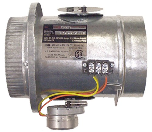
Fresh Air Damper
- Foam seal for quiet effective air control.
- Simple to install in-line with existing air ducts.
- Durable spring motor drive with nylon bearings.
- 24VAC Motor 5 watts, continuous stall protected.
Warning!
If you are uncomfortable wiring or do not completely understand the equipment, it is best to hire a professional for help. Ensure to follow all electrical and building codes including local codes relating to air control.
The wiring for motorized fresh air dampers varies depending on heating and cooling requirements.
Wiring Fresh Air Dampers in Cold Climates

Parts List
In cold climates, wiring the damper in parallel with the furnace W and C terminals is sufficient when only heating is required. When the thermostat calls for heat, the thermostat R and W switch closes, applying 24VAC from the furnace R terminal to the furnace W terminal. When the furnace W terminal receives 24VAC,the furnace starts. At this point, the motorized damper opens to supply fresh air while the furnace is running. Once the thermostat reaches the desired temperature, the thermostat R and W switch opens, removing the 24VAC from the furnace W terminal. The furnace then shuts down and the motorized fresh air damper closes to provide comfort and conserve energy.
Toggling the 3-way override switch to the red wire, “override” position, applies 24VAC from the furnace R and C terminals to the damper motor. This holds the fresh air damper open until the switch returns to the white wire “normal” position.
Wiring Fresh Air Dampers in Hot Climates

In hot climates, wiring the damper in parallel with the air handler Y and C terminals is sufficient when only cooling is required. When the thermostat calls for cooling, the thermostat R and Y switch closes, applying 24VAC from the air hadler R terminal to the air handler Y terminal. When the air handler Y terminal receives 24VAC,the air conditioner starts. At this point, the motorized damper opens to supply fresh air while the air conditioning is on. Once the thermostat reaches the desired temperature, the thermostat R and Y switch opens, removing the 24VAC from the air handler Y terminal. The air conditioner then shuts down and the motorized fresh air damper closes to provide comfort and conserve energy.
Toggling the 3-way override switch to the red wire, “override” position, applies 24VAC from the air handler R and C terminals to the damper motor. This holds the fresh air damper open until the switch returns to the yellow wire “normal” position.
Wiring Fresh Air Dampers in Mixed Climates

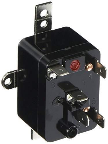
Damper Relay
General purpose relay with a 24V coil. Suitable for switching circuits in various heating, ventilation, and air conditioning systems. It has five spade terminals for quick, reliable connections for single pole double throw switching capabilities.
Parts List
- Heating and cooling damper relays
- Fresh air damper (power open)
- Thermostat wire
- Insulated terminals and crimping tool
Mixed climates that require heating and cooling need additional control relays to open the fresh air damper during each season. Do NOT wire the fresh air damper in parallel with the furnace W, Y, and C terminals. Wiring the damper in parallel would cause both the heating and air conditioning to operate at the same time.
Heating Cycle Fresh Air Damper Operation
When the thermostat calls for heat, the thermostat R and W switch closes, applying 24VAC from the furnace R terminal to the furnace W terminal. Once the furnace W terminal receives 24VAC, the furnace starts and the coil of the heating damper relay energizes. When the heating damper relay energizes, the 2-4 contact closes and the 4-5 contact opens. This opens the damper by applying 24VAC from the furnace R and C terminals to the damper motor. The 24VAC flows through the heating damper relay 2-4 contact and cooling damper relay 4-5 contact. At this point, the motorized damper is open, supplying fresh air while the furnace is operating.
Once the thermostat reaches the desired temperature, the thermostat R and W switch opens, removing the 24VAC from the furnace W terminal. The furnace then shuts down and the heating damper relay de-energizes. The 2-4 contact of the heating damper relay opens, removing the 24VAC from the furnace R terminal to the motorized fresh air damper. At the same time, the motorized fresh air damper closes to provide comfort and conserve energy.
Cooling Cycle Fresh Air Damper Operation
When the thermostat calls for cooling, the thermostat R and Y switch closes, applying 24VAC from the furnace R terminal to the furnace Y terminal. Once the furnace Y terminal receives 24VAC, the air conditioner starts and the coil of the cooling damper relay energizes. When the cooling damper relay energizes, the 2-4 contact closes and the 4-5 contact opens. This opens the damper by applying 24VAC from the furnace R and C terminals to the damper motor. The 24VAC flows through the cooling damper relay 2-4 contact. At this point, the motorized damper is open, supplying fresh air while the air conditioner is operating.
Once the thermostat reaches the desired temperature, the thermostat R and Y switch opens, removing the 24VAC from the furnace Y terminal. The air conditioner then shuts down and the cooling damper relay de-energizes. The 2-4 contact of the cooling damper relay opens, removing the 24VAC from the furnace R terminal to the motorized fresh air damper. At the same time, the motorized fresh air damper closes to provide comfort and conserve energy.
Closing the override switch, applies 24VAC from the furnace R and C terminals to the damper motor. The 24VAC flows through the heating damper relay 4-5 contact. This provides the ability to open the fresh air damper when neither heating nor cooling is in use.
Ductwork Leakage Testing
Measuring ductwork leakage with the use of specialized equipment (calibrated fan, blower door, and differential pressure gauges) quantifies the amount of leakage within the system. Results from existing non-sealed or roughed in systems, gives a starting point as to how severe the leakage is. Results after sealing determines how airtight the system has become as well as if the system meets energy codes or green building programs requirements.
Total leakage and leakage to the outside are the two types of duct leakage tests performed when evaluating the duct system air-tightness.
Total Leakage
The total leakage pressurization test typically subjects duct systems to a uniform test pressure of 25 Pascals (Pa). This test measures both leakage to the outside of the building envelope (attics, crawlspaces, and garages), as well as leakage inside the building.

Total Leakage Test Preparation
- Adjust thermostat controls or turn off power to the air handler or furnace fan to prevent fan operation during testing.
- Turn off all building exhaust fans (bathroom, range hood, etc.) and clothes dryers.
- Connect the calibrated fan grille adapter and ducting to either a large return grille or directly to the air handler / furnace cabinet.
- Temporarily seal all supply and return registers with grille mask tape.
- Seal the building fresh air intake if it connects to the return air ductwork. Temporarily seal the intake vent opening on the outside of the building using grille mask tape.
- Remove air handler / furnace filter.
- Open a window or door to the outside to prevent changes in building pressure when the calibrated duct fan is running.
Total Leakage Test Results
Increasing the speed of the calibrated fan increases the airflow through the fan. The pressure increase within the duct system, results when more air flows through the fan. Fan speed adjustments continue until the pressure within a supply duct register reaches 25 Pa.
The differential pressure of the fan determines the velocity of the airflow entering the duct system.
\small {Airflow\; Velocity }_{ (ft/min) }=4005\times \sqrt { \Delta P} \\ \Delta P=25\; Pa\; test\; pressure
The ring size chosen for the total leakage test determines the cross-sectional area of the calibrated fan.
The airflow in cubic feet per minute displayed on the right-hand side of the pressure gauge derives from the following equation:

This airflow {\small (CFM }_{ 25 }) value represents the total duct leakage rate of the system. Duct sealing results in tighter ductwork systems that require less airflow to establish the 25 Pa duct pressure. Converting this value into a percentage determines if the duct leakage rates meets energy codes or green building program requirements.
Example
A 2500 square foot building requires 100 CFM flowing through the duct fan to pressurize the duct system to 25 Pa. What is the overall percentage of total duct leakage?
\small \begin{alignedat}{3}\%\, Duct\, Leakage&={CFM}_{25}/Cond.\, Floor\, Area \\ \%\, Duct\, Leakage&=100{CFM}_{25}/{2500ft}^{2} \\ \%\, Duct\, Leakage&=4.0\% \end{alignedat}
Note
The International Energy Conservation Code (IECC) is a building code that establishes the minimum design and construction requirements for energy efficiency. The IECC duct leakage testing requires air leakage rates of less than four percent of conditioned floor area.
Leakage to the Outside
The leakage to the outside test only measures the amount of duct leakage exiting the building envelope (attics, crawlspaces, and garages). Since leaks outside the building envelope are a major source of energy loss, quantifying and reducing this leakage is important.
The test typically subjects both the duct systems and building to a uniform test pressure of 25 Pa. First, the blower door pressurizes the building. Once the building reaches test pressure, the duct fan pressurizes the ductwork until the pressure difference between the ducts and the building is zero Pa. Since the test pressurizes both the building and ductwork simultaneously to the same pressure, no leakage will occur within the building during the test.

Leakage to Outside Test Preparation
- Same as total leakage with the exception that all exterior doors and windows must be closed.
- Open all interior doors.
- Setup blower door and pressurize building to 25 Pa.
Leakage to Outside Test Results
The airflow \small { (CFM }_{ 25 }) value through the calibrated duct fan represents the leakage rate to outside.
Example
A 2500 square foot building requires 80 CFM flowing through the duct fan to establish a differential pressure between the building and ductwork of zero Pa. What is the overall percentage of duct leakage to the outside?
\small \begin{alignedat}{3}\%\, Duct\, Leakage&={CFM}_{25}/Cond.\, Floor\, Area \\ \%\, Duct\, Leakage&=80{CFM}_{25}/{2500ft}^{2} \\ \%\, Duct\, Leakage&=3.2\% \end{alignedat}
Conclusion
Air leakage in forced air duct systems is a major source of energy waste in both new and existing buildings. Sealing and testing leaky ductwork is a cost effective energy improvement. HVAC duct sealing results in lower utility bills as well as a more comfortable living environment.
Save Energy – Save Money – Live Comfortably – Seal HVAC Ductwork
Parts & Material Required
- UL181-rated Duct Mastic
- UL181-rated HVAC Foil Tape
- Self-Adhesive Mesh Drywall Tape
- Disposable Gloves
- Paint Brushes
- Drop Cloths (when applying mastic above carpeted areas)
- Fresh Air Damper (Power Open)
- Thermostat Wire
- Heating and Cooling Damper Relays
- Insulated Terminals and Crimping Tool
Related Content
How to Connect & Setup a Nest Thermostat to Function as a Humidistat
How set up a Nest Thermostat with a whole house dehumidifier