Dimming LED lights allows you to control light output levels to create an ambiance suitable for the occasion. Low levels of light may be desirable to set the mood for movie nights, or to create a relaxing environment before going to bed. Incandescent lights are simple and effective too dim; however, they are not energy efficient. Dimming LED lights is more complex which consequently creates issues if done incorrectly. Dimming LED lights properly mirrors the ambiance created from incandescent dimming and is much more energy efficient.
Energy savings from LED lighting
When you use incandescent or halogen bulbs for lighting, the energy consumed by these lights adds up to in a significant portion of your home’s overall energy usage. Incandescent and halogen bulbs waste a considerable amount of energy in the form of heat while producing light. LED bulbs do not produce much heat and are therefore up to 90% more energy efficient. Replacing all your incandescent and halogen bulbs with equivalent LED bulbs will considerably reduce your energy consumption and energy bill.
LED lighting wattage and equivalent wattage ratings
Packaging for LED lights often includes labels with wattage and equivalent wattage ratings. This can be confusing and it is due to a consumer learning curve of how we traditionally purchased light bulbs. The wattage refers to the actual power consumption of the LED light without dimming the bulb. The equivalent wattage is a representation of the bulb brightness (lumen output) compared to that of an incandescent bulb. Incandescent bulbs vary in brightness based on the power they consume. Incandescent bulbs have approximately the following lumen output:
\begin{alignedat}{4}100W\; &\approx \; 1600 \hspace{1mm} &lumens \\ 75W\; &\approx \; 1100 &lumens \\ 60W\; &\approx \; 800 &lumens \\ 40W\; &\approx \; 450 &lumens
\end{alignedat}
Example
For a light output of 450 lumens an incandescent bulb will typically consume 40W of power. Comparatively a LED bulb with the same light output, will typically consume 5.5W of power.
\frac { 5.5W }{ 40W } =13.75\%5.5 watts equals 13.75% of the power consumed to produce the same light output, meaning it is 86.25% more efficient.
Kelvin color temperature scale
The Kelvin color temperature scale is used to describe the light appearance produced from a light bulb and is measured in oK. The light appearance of the scale gradually changes from warm on the far left to cool on the far right. Warm lights are more relaxed in nature and are typically located in living rooms and bedrooms. Cool lights are more energetic in nature and are typically located in work environments like laundry rooms, garages, and office spaces. LED lights are generally available throughout the entire Kelvin color temperature scale.
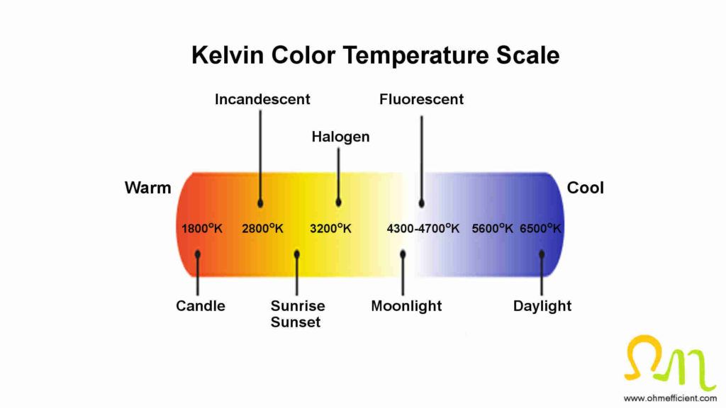
A lot of people make to mistake of buying LED lights without paying attention to the Kelvin rating on the package. If they were expecting something warm and relaxing, it may come as a surprise to see an energetic cool color when they turn it on for the first time. Don’t make this mistake; be sure to look at the Kelvin rating before buying your next set of LED lights.


How dimmer switches work
The most common dimmer used for lighting is the Pulse Width Modulation (PWM) dimmer. These dimmers use electronic components to cut out sections of the sinusoidal voltage waveform. This reduces the root-mean-square voltage applied to the light and hence reduces the power supplied to the light. The amount of light output from conventional incandescent lighting is directly related to the amount of power supplied to the light. The light is at its brightest level when the least amount of voltage is cut out of the sinusoidal waveform. The light is at its dimmest level when the largest amount of voltage is cut out of the sinusoidal waveform.
LED electronic drivers
The direct correlation between the amount of power the light receives and the light brightness level does not apply when dimming LED lights. As mentioned previously, dimming LED lights is more complex. Each LED light bulb (or LED luminarie) has electronic circuits built within it. These electronic circuits are referred to as the LED driver. One of the components within the LED driver is the pulse width modulation controller. This controller receives signals regarding the degree of voltage cut out, supplied from the dimmer switch. The PWM controller produces an output signal that can be manipulated, but is proportional to this input. This output signal is then applied to more electronic components that produce constant current pulses that are supplied to the LEDs within the bulb.
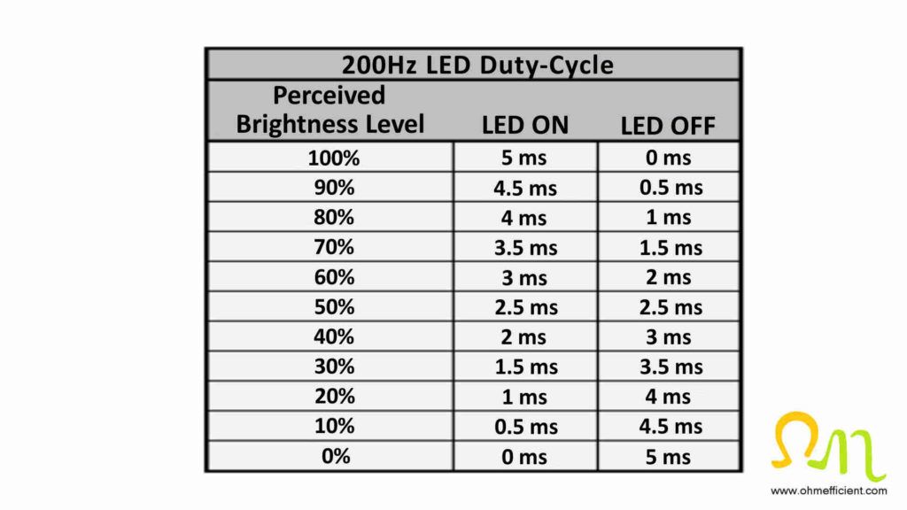
Constant current pulses vary in duty-cycle depending on the output from the PWM controller. The duty-cycle refers to the amount of time the constant current pulse is on over the duration of one cycle. For example, if the output frequency of the PWM is 200 hertz, one cycle is equal to 1/200 = 5 milliseconds. Dimming LED lights to 50% brightness correlates to setting the dimmer switch to the half way position. This would be a duty cycle of 50% where the constant current pulse is ON for 2.5 milliseconds and OFF for 2.5 milliseconds. Likewise, if the dimmer is set to 20% the constant current pulse are ON for 1 millisecond and OFF for 4 milliseconds. The human eye cannot see this rapid on/off cycle of the LEDs, but rather perceives changes in light brightness levels.
Pulse width modulation dimmers
PWM dimmers come in two forms: Forward Phase and Reverse Phase. Both forward phase and reverse phase are capable of dimming LED lights as long as the LED driver within the bulb is compatible. The Reverse phase dimmer is more suitable for dimming LED lights; however it comes with a higher price tag.
LED dimmer switch forward phase C*L
Forward phase dimmers utilize an electronic component known as a TRIAC (Triode for Alternating Current) to cut out sections on the leading edge of the sinusoidal voltage waveform. Other dimmer electronic components sense the zero crossing of the voltage input. Upon zero crossings, a delay period starts (varies depending on dimmer slide position) after which the TRIAC triggers to conduct. When the TRIAC is in conduction, the load receives voltage and current. It is important to understand that a TRIAC is only able to switch into a voltage. In order for the TRIAC to stop conduction, the current through it must drop below its holding current value. Therefore the TRIAC will continue to conduct until the next zero crossing, or the load current drops below the holding current value. When utilized in a dimmer circuit, a TRIAC is essentially an electronic off/on switch where only the on portion is controlled.


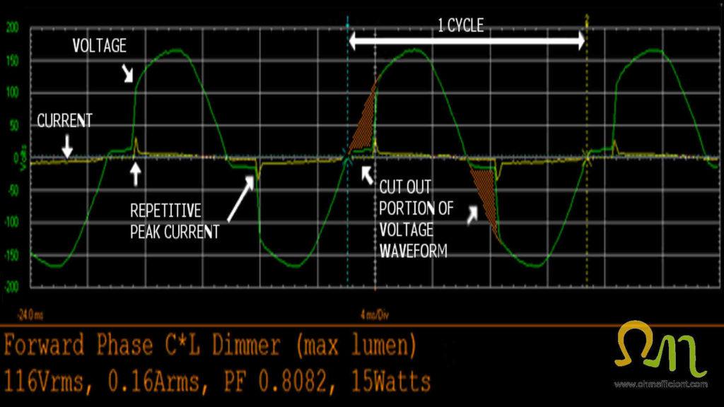
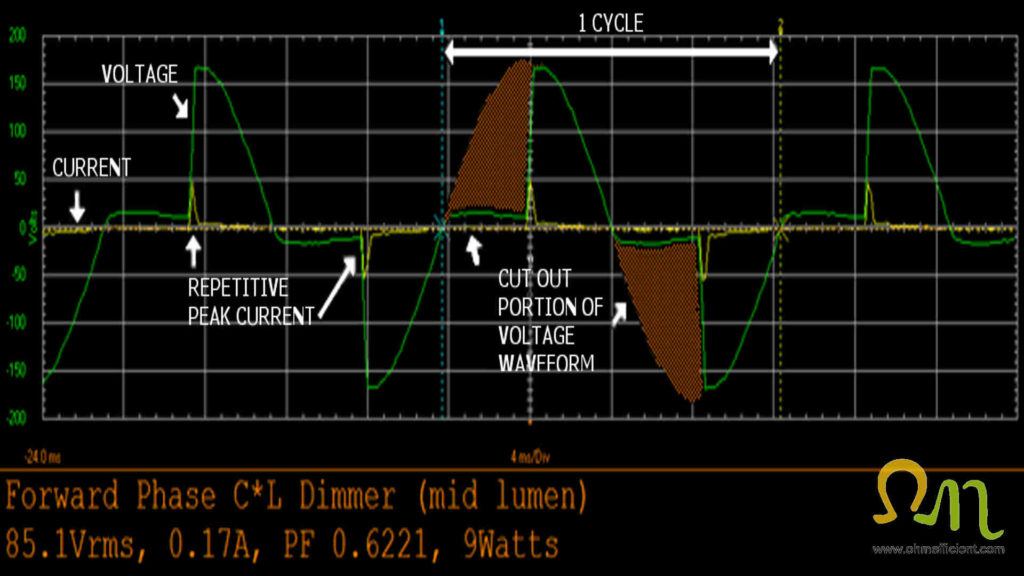
The following oscilloscope waveforms represent a forward phase C*L dimmer and three 5.5W Philips dimmable LED bulbs at varying brightness levels.
Note
Dimmer set to highest setting for maximum brightness, as a result, a small portion of the waveform is cut out.
Note
Dimmer set to middle setting for 50% brightness, as a result, half of the waveform is cut out.
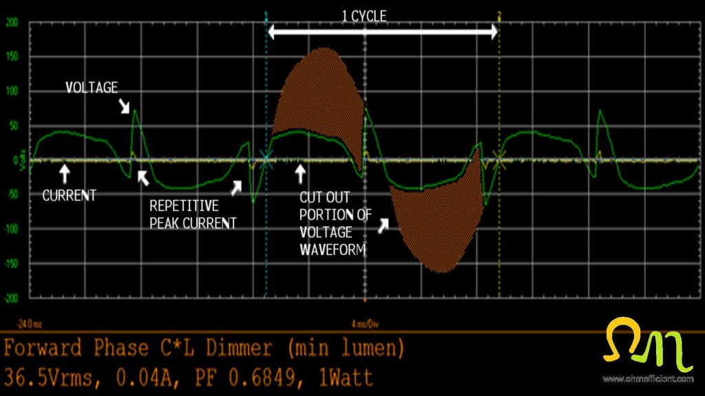
Note
Dimmer set to lowest setting for minimum brightness, as a result, a large portion of the waveform is cut out.
The dimming performance using this combination of dimmer and bulb is satisfactory. The bulbs dim from 90.9% to 6.1% of rated value. The LED lights produce a slight buzzing sound. Refer to the “LED dimming issues and how to solve them” section below to learn more about what causes LED’s to buzz.
Why existing dimmers may not be suitable for dimming LED lights
Forward phase dimmers were originally designed to be used with incandescent lights. Incandescent lights are purely resistive loads and typically have a higher wattage of 40/60/100 watts per bulb. The higher wattage of the incandescent bulbs results in larger currents flowing through the TRIAC within the dimmer. TRIAC’s require a minimum amount of current to remain in conduction. This minimum current is known as “holding current”. If the load current drops below the required holding current value, the TRIAC will stop conducting and cut out. Power will not be supplied to the light until the delay period after the next zero crossing, were this cycle repeats. This could appear as a flickering effect of the LEDs.
Forward phase dimmers that were originally designed for incandescent lights generally have a higher holding current value. This holding current is usually higher than the amount of current drawn from LED lighting, especially when dimmed. The TRIAC’s in forward phase C*L dimmers have a lower holding current value. When a forward phase C*L dimmer is paired with an LED bulb with a driver compatible with forward phase, satisfactory dimming will be achieved.
LED dimmer switch reverse phase ELV
Reverse phase dimmers utilize an electronic component known as a MOSFET (Metal Oxide Semiconductor Field Effect Transistor), or an IGBT (Insulated Gate Bipole Transistor) to cut out sections on the trailing edge of the sinusoidal voltage waveform. Other dimmer electronics sense the zero crossing of the voltage input. Upon zero crossings, the MOSFET or IGBT triggers and conducts until the delay period (varies depending on dimmer slide position) lapses. When the MOSFET or IGBT is in conduction, the load receives voltage and current. A MOSFET or an IGBT can be switched off regardless of the current flowing through them. As a result, this allows for the voltage and current to be interrupted throughout the entire cycle.
Reverse phase dimmers also apply a resistance that fades the voltage to zero once the MOSFET or IGBT switches off. When utilized in a dimmer circuit, a MOSFET or an IGBT is essentially an electronic on/off controllable switch.


The following oscilloscope waveforms represent a reverse phase dimmer and three 5.5W Philips dimmable LED bulbs at varying brightness levels.
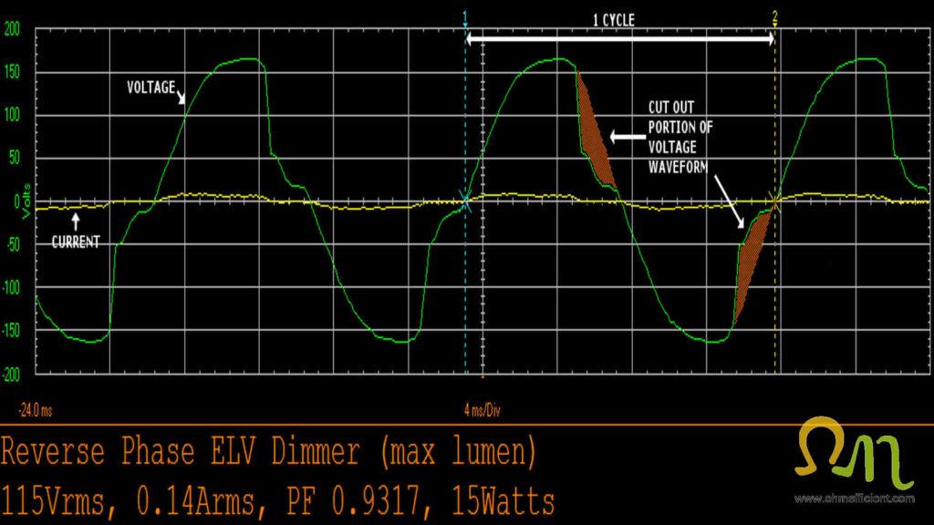
Note
Dimmer set to highest setting for maximum brightness, as a result, a small portion of the voltage waveform is cut out.
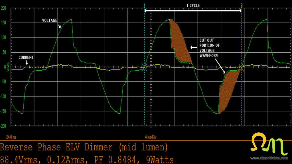
Note
Dimmer set to middle setting for 50% brightness, as a result, half of the voltage waveform is cut out.
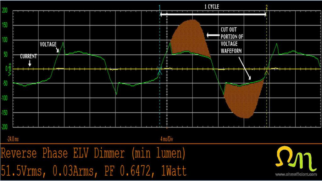
Note
Dimmer set to lowest setting for minimum brightness, as a result, a large portion of the voltage waveform is cut out.
The dimming performance using this combination of dimmer and bulb is excellent. The bulbs dim from 90.9% to 6.1% of rated value. Unlike the forward phase dimmer, there is no buzzing sound coming from the bulbs throughout the entire dimming range.
Reverse phase dimmers require a neutral wire
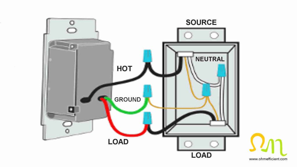
Reverse phase dimmers utilize a third wire that is connected to neutral. This wire provides power to the dimmer electronic components and additionally helps the dimmer stay synchronized with the input sinusoidal voltage. This synchronization helps with better control of the MOSFET or IGBT triggering.
Some older homes may not have a neutral wire brought into the light switch electrical box. If you live in an older home, ensure you have a neutral wire before purchasing a reverse phase dimmer.
Maximum dimmer switches ratings LED versus incandescent
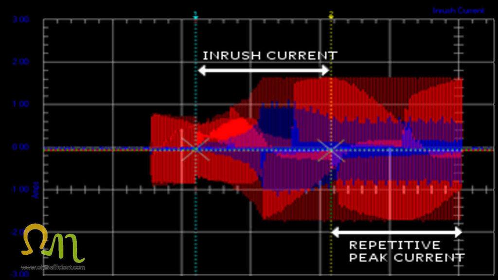
Repetitive peak current
Forward phase dimmer switches have two different maximum ratings; one for use with LED lighting and one for use with incandescent lighting. The LED lighting maximum rating is less than the incandescent maximum rating. When dimming LED lights using a forward phase dimmer, the continuous abrupt switching performed by the TRIAC creates repetitive peak currents. These repetitive peak currents differ in magnitude depending on where in the waveform the voltage switches on. Additionally, repetitive peak currents will differ depending on the design and construction of the LED driver. Note: Manufactures build LED drivers in various ways that differ between manufacture and model.
North American utilities operate at 60 hertz and these repetitive peak currents occur twice per cycle. This means that for every 1 second, there are 120 repetitive peak currents. European utilities operate at 50 hertz and therefore have 100 repetitive peak currents every second. These repetitive peak currents increase the stress on the dimmer which therefore needs to be addressed for electrical safety. Dimmer manufactures analyze their dimmer circuits and may use worst case LED behavior to de-rate the maximum load rating.
Note
You can read online about rules of thumb regarding maximum LED loading for dimmers. Don’t follow rules of thumb for electrical safety; follow the dimmer manufactures maximum load rating!
Inrush current
Inrush current refers to the initial momentary maximum current draw when switching on a load. Both LED and incandescent lighting exhibit inrush currents, but for different reasons. When incandescent lights have been off for a while, there metallic element is cool and has a lower resistance. When turning on an incandescent light, the inrush current draw occurs until the metallic element reaches operating temperature (higher resistance). Similarly, when turning on an LED light, the inrush current draw occurs until the LED driver capacitive circuits charge.
Minimum rating for LED dimmer switches
Holding current
Minimum ratings are required for forward phase dimmers to ensure the holding current of the TRIAC is maintained throughout the whole LED dimming range. Forward phase C*L dimmers have lower minimum loads then conventional incandescent forward phase dimmers. Forward phase C*L dimmers don’t typically give the minimum wattage for LED lighting required because of the numerous LED driver designs. It becomes more of a trial and error method to see what dimmer works well with what bulbs. Luckily, there are compatibility lists that you can look up online to see what the manufactures suggest.
Leakage current
Dimmer filtering and sensing electronic components require small amounts of power even while the dimmer is off. This results in a small leakage current that flows through the LED driver when the light should be off. Cheap LED drivers provide a path for current flow while the dimmer is on; however, they don’t provide a path for current flow when the dimmer is off. The LED driver capacitive circuits therefore slowly charge from this small amount of leakage current through the dimmer. This can lead to erratic flashing of the LED bulb while the capacitive circuit goes through the charge/discharge cycles. It could also result in the LED bulb to remain on with a low level of light.
Adding more LED bulbs to the dimmer may meet the leakage current requirement by distributing it over more LED bulbs. Most reputable brands of LED bulbs use LED drivers that utilize a constant current source. The constant current source provides a path for current to flow while the dimmer is off. The LED bulb therefore remains off when the dimmer switch is off and leakage current is flowing through it.
LED dimming issues and solutions
Flickering occurs when dimming LED lights
Flickering is when the human eye is able to see the on/off modulation of light output from the LED bulb. This occurs when LED bulbs connect directly to alternating current (AC) supplies without an LED driver. Pulse width modulation (PWM) dimmers cut out a portion of the sinusoidal voltage waveform each half cycle. The LED turns on and off 120 times per second and depending on the amount of voltage cut out of the waveform; the human eye may be able to see an annoying flickering of the light output.
Solution
Replace the LED bulbs you wish to dim with new dimmable ones that incorporate an LED driver.
Modern LED bulbs incorporate an LED driver that supplies the LEDs with direct current (DC). These LED drivers also incorporate capacitors to store a charge. Pulse width modulation (PWM) dimmers cut out a portion of the sinusoidal voltage waveform each half cycle. The LED driver therefore uses the stored energy from its capacitors to be able to continuously supply the LED with direct current. Dimmers originally designed for incandescent bulbs have a higher holding current value. If the LED bulbs don’t have a large enough load to maintain this holding current value, the TRIAC will stop conducting. When this occurs, the capacitors within the LED driver may not charge and an erratic style of flickering may occur.
Solution
Replace the dimmer with one that is compatible with your dimmable LED bulbs.
Ghosting occurs when dimming LED lights
Ghosting is when a dimmer switch is off; however, the LED light stays on with low levels of light output. As mentioned in the “Minimum rating for LED dimmer switches” section above, a dimmer’s filtering and sensing electronic components always require small amounts of power. This results in a small leakage current that flows through the LED driver, even when the dimmer switch is off.
Solution
Replace the dimmable LED bulb(s) with ones made by a reputable manufacturer. The LED driver will utilize a constant current source which provides a path for leakage current to flow while the dimmer is off. The LED bulb will remain off when the dimmer switch is off and leakage current is flowing through it.
Buzzing occurs when dimming LED lights
Buzzing is when you can hear a humming noise coming from the LED lighting. The buzzing comes from the LED drivers filter components and its cause is from the sudden rise in current each time the TRIAC is triggered. If you pay close attention to the buzzing noise, you can hear it increase as the lights dim to 50% and then fade as the lights dim to their lowest level. This is because the amplitude of the sudden rise in current is greatest at the 50% level and lessens near the dimmest level.
Solution to reduce noise
Replace your conventional dimmer switch with a forward phase C*L dimmer. Forward phase C*L dimmers incorporate an internal choke or filter to even out the current spikes. This will drastically reduce the humming noise coming from the LED lighting compared to conventional dimmer switches.
Solution to eliminate noise
Replace your conventional dimmer switch or forward phase C*L dimmer with a reverse phase electronic low voltage dimmer. Reverse phase dimmers, switch out the voltage and apply a resistance to fade the voltage to zero, thereby eliminating current spikes.
Drop out occurs when dimming LED lights
Drop out is when LED bulbs don’t dim from 100% to 1%, they stop dimming while light output remains high. For example, the dimmer may be at its lowest setting and the light may still be 50% bright. The reason this occurs is that leakage current is affecting the dimming range, which is preventing lower light levels.
Solution
Replace the dimmable LED bulb(s) with ones made by a reputable manufacturer. The LED driver will utilize a constant current source which provides a path for leakage current to flow.
Pop on occurs when dimming LED lights
Pop on is the exact opposite of drop out. When turning on a dimmer that is on at low setting, the LED bulbs turn on at a level much greater level. Similarly to drop out, the reason this occurs is that leakage current is affecting the dimming range which is preventing lower light levels.
Solution
Replace the dimmable LED bulb(s) with ones made by a reputable manufacturer. The LED driver will utilize a constant current source which provides a path for leakage current to flow.
Dead travel occurs when dimming LED lights
Dead travel is when the dimmer setting is adjusted without any noticeable change in light output. The reason why this occurs is that the minimum load requirements of the dimmer switch have not been met.
Solution 1
Add more LED bulbs to the dimmer to meet the minimum load requirements of the dimmer.
Solution 2
Replace your conventional dimmer switch or forward phase C*L dimmer with a reverse phase electronic low voltage dimmer. Reverse phase dimmers generally produce smooth continuous operation over the entire dimming range.
Electromagnetic Interference (EMI)
LED drivers generate an electromagnetic field that varies depending on the frequency at which it produces a constant current pulse. Strong electromagnetic fields create problems for other electronic devices operating in close proximity; this is known as electromagnetic interference. LED drivers made by reputable manufacturers incorporate filters to limit the degree of electromagnetic field emitted from their product. If you notice problems with other electronic devices while in close proximity to LED lighting, there is a good chance the LED driver does not have electromagnetic interference filters. Cheap bulbs usually don’t have these filters and therefore produce varying levels of EMI.
Solution
Replace LED bulb(s) with ones made by a reputable manufacturer.
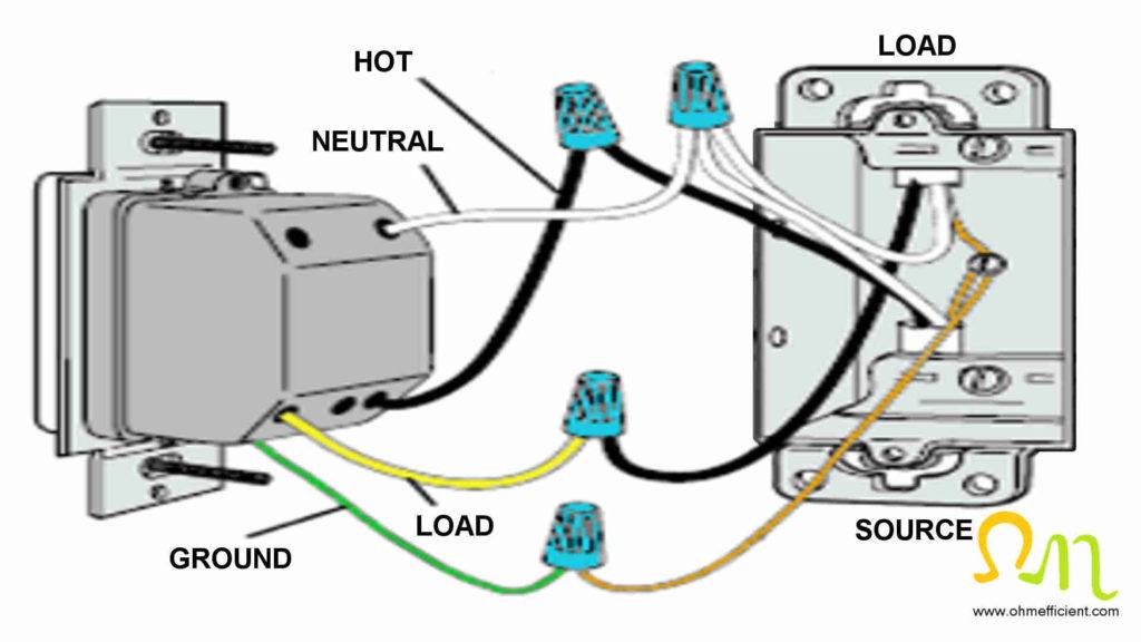
Wiring dimmer switches
Installing a dimmer switch is a simple do it yourself task. Be sure to follow the safety procedures included with the dimmer switch. Once complete, the lights will be dimmable allowing you to control the room ambiance with the added benefit of reducing energy consumption.


Conclusion
LED lighting is up to 90% more energy efficient than traditional lighting methods which decreases energy consumption considerably. LED bulbs can be purchased throughout the Kelvin color temperature scale, allowing for selection of light appearance (warm to cool). Dimmable LED drivers coupled with LED dimmers allows for control of ambiance. Dimming LED lights can be more challenging than dimming traditional lighting, however, when done correctly, controlling ambiance is achieved much more efficiently.
Based on the numerous issues (flicker, ghosting, buzzing, drop out, pop in, dead travel, and EMI); it is best to purchase LED lighting and dimmers from reputable manufacturers. Reputable manufactures build their products with better quality electronics and design to minimize these issues. When it comes to dimming LED lights, you get what you pay for.
Parts and tools
Wire Strippers
Multi-Meter
Non-Contact Voltage Tester
Utility Knife
Forward Phase C*L Dimmer
Reverse Phase ELV Dimmer
Dimmable LED bulbs
Related articles

