
This article explains how to connect a Nest thermostat to control room temperature using a gas fireplace. Wiring diagrams are included for the two most common types of ignition systems found in gas fireplaces. These ignition systems include the millivolt ignition (standing pilot / continuous pilot) and the intermittent pilot ignition IPI (electronic ignition). Additionally, to gain a better understanding, this article explains how each fireplace ignition system operates.
How a direct vent gas fireplace provides heat
Direct vent gas fireplaces have an empty metal surrounding which captures heat from the flames within the firebox. When the temperature within this surrounding increases above the thermal snap switch temperature setting, the fireplace fan turns on. The front of the fireplace has an upper and a lower grill, which both connect directly to the firebox surrounding. The bottom grill draws in cool air from the room. The cool air absorbs heat as it circulates around the firebox surrounding. The air that exits the surrounding through the top grill then reenters the room as warm air. Additionally, heat from the flames within the firebox provide radiant heat into the room through the front glass door. Therefore, direct vent gas fireplaces deliver radiant as well as convective heating.
The fresh air intake and exhaust outlet of the fireplace, attach directly to the firebox area by connecting through the metal surrounding. The fresh air intake provides air for combustion. This combustion air comes straight from outside. Therefore, no indoor air enters into the sealed firebox combustion chamber. This increases the overall efficiency of direct vent fireplaces, as no conditioned indoor air exits the building. The exhaust outlet, vents the gas fireplace emissions directly outside the building through the flue. Therefore, under normal fireplace operation, no emissions should enter inside the room.

Millivolt ignition fireplace
Millivolt ignition fireplaces are commonly referred to as either continuous pilot or standing pilot fireplaces. As the name implies, the pilot light stays lit 24 hours a day, 7 days a week. Depending on the fireplace log set orientation, you can typically see a small blue flame burning at the pilot assembly. The pilot assembly includes a thermopile, pilot cap, piezo igniter electrode, as well as a thermocouple.
The thermopile wires connect to the millivolt gas valve TPTH and TP terminals. TH and TP are the abbreviations for thermostat and thermopile respectively. Gas supply tubing connects the safety/pilot valve within the millivolt gas valve to the pilot cap. The igniter electrode lead typically connects to a piezo igniter push button. The thermocouple lead connects to the solenoid coil of the safety/pilot valve within the millivolt gas valve.

Millivolt ignition fireplace – sequence of operation
- Manually open the safety/pilot valve by turning and depressing the control knob while in the “pilot” position.
- Simultaneously press the piezo igniter repeatedly to create sparks to ignite the gas flowing from the safety/pilot valve.
- Once the pilot light has a flame, continue depressing the control knob for a few more seconds to warm up the thermocouple. The pilot light should remain lit after releasing the control knob.
- Turn the control knob to the ON position.
- Place the ON/OFF switch in the ON position or set the thermostat to call for heat.
- The main gas valve receives voltage from thermopile and opens as a result.
- The main burner will then ignite.
- When either the thermostat reaches its temperature setting or the ON/OFF switch turns OFF, the main valve solenoid no longer receives the thermopile voltage. The main gas valve will then close.
Wiring a 24VAC Nest thermostat to a millivolt gas fireplace
The Nest thermostat installation requires either a wired or a plugin 120/24 volt thermostat transformer. The transformer supplies the Nest thermostat with 24VAC across the RH and C connectors. This voltage powers the Nest thermostat as well as charges the thermostats internal battery. Additionally, this voltage controls the operation of the 24VAC control relay, which turns the fireplace on and off.
Wiring a single white wire between the Nest’s W1 connector and terminal 3 of the control relay allows the Nest to control the fireplace. A blue jumper wire connects terminal 1 of the control relay to the 24VAC common terminal C of the wired or plugin transformer. The black and red of the 18/2 thermostat wire connects terminals 2 and 4 of the control relay to the millivolt gas valve TPTH and TH terminals. When heat is called for, the Nest closes its “switch” and applies 24VAC to the coil of the control relay. The contact on the control relay will then close. The control relay contact then supplies the thermopiles 750mVDC across the main gas valve’s solenoid coil. Applying 750mVDC across the main gas valve solenoid, opens the valve and allows gas to flow to the main burner.
Selecting either a plugin or wired transformer depends on the layout of the gas fireplace as well as accessibility to a 120V receptacle. If the layout of the fireplace has a 120V receptacle and space available to install a control relay, the plug-in transformer is best. If the fireplace does not have a receptacle, installing a wired transformer and control relay within a metallic junction box is required.
Note
The thermostat wiring within the fireplace needs to be rated for 105oC.
Nest thermostat and millivolt fireplace wiring diagram

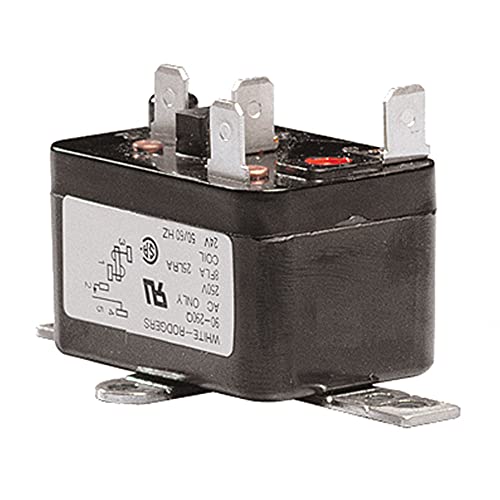
Control Relay
General purpose relay with a 24V coil. Suitable for switching circuits in various heating, ventilation, and air conditioning systems. It has four spade terminals for quick, reliable connections for single pole normally open switching capabilities.
Parts required
- Nest Thermostat
- 120/24VAC Transformer
- Thermostat Wire
- High Temperature Wire
- Control Relay
- Terminal Crimps & Crimping Tool
- Junction Box
- Cable Glands
Nest thermostat and millivolt fireplace wiring diagram using a plugin transformer

Plugin Transformer
Compatible with smart thermostats like Nest, Ecobee, etc. and other devices that require constant 24 volt power for operation. UL listed and has built in 2A thermal fuse short circuit protection.

Parts required
- Nest Thermostat
- 120/24VAC Plugin Transformer
- Thermostat Wire
- High Temperature Wire
- Control Relay
- Terminal Crimps & Crimping Tool
- Wire Nuts
Millivolt gas fireplace operation
The following explains how the components within the millivolt gas fireplace work together. Additionally, this section will provide you with a better understanding of how the millivolt fireplace works.
Millivolt gas fireplace pilot assembly
The millivolt pilot assembly has two functions. The first function is to provide proof of flame to the millivolt gas valve’s safety/pilot and main solenoid coils. The flames to the left and right of the pilot cap in the picture below provide this functionality. The other function the pilot assembly provides is to ignite the main burner when the main gas valve opens. The flame directed towards the main burner in the picture below is for this purpose.

Millivolt Gas Fireplace Pilot Assembly
Replacement pilot assembly for Majestic fireplace models but may also fit on many of the other manufacturers and models based on fuel type and compatibility. Fuel type: Natural Gas.

Piezo igniter electrode
Pushing the piezo igniter push button results in a momentary electrical arc between the pilot assembly electrode and pilot cap. This momentary electrical arc provides the heat required to ignite the pilot assembly for the first time. Lighting a standing pilot fireplace for the first time typically consists of placing the control knob on the millivolt gas valve in the pilot position. Once the knob is in the pilot position, depressing the knob manually opens the safety/pilot valve. Gas will then flow through the tubing from the millivolt gas valve to the pilot cap. Pressing the piezo igniter push button develops an arc, which then ignites the gas. Once the pilot flame is lit, continue to hold the control knob down until a strong pilot flame is present, and then slowly release the knob. If everything is functioning properly, the pilot flame should remain on at this point.
The piezo igniter consists of a metallic oxide based piezoelectric ceramic material PZT. PZT is composed of lead Pb, zirconium Zr and the chemical compound titanate. When a piezoelectric material is deformed, it develops an electric charge. A spring-loaded hammer within the piezo igniter push button hits and deforms the PZT each time the button is pressed. The PZT deformation creates a momentary high voltage (~18kV) that is capable of arcing a distance of 2 to 3 millimeters. This high voltage arcs from the tip of the pilot assembly electrode to the grounded pilot cap.
Piezo Igniter
- Output voltage: >=18KV, Pressure: 3.0±0.5kg.
- Applicable gas: LPG, NG, Temperature resistance: -20°C~120°C.
- No battery needed, just one press, one press one spark.

Thermocouple
The thermocouple within the fireplace pilot assembly verifies the presence of the pilot flame. When the thermocouple circuit does not detect a flame at the pilot assembly, it closes the safety/pilot valve. This ensures that the gas supply to the pilot assembly shuts off, preventing the home from filling with gas and creating an explosion hazard.
Thermocouples consist of two wire leads made from dissimilar metals that join at one end to form two junctions. The point where the two dissimilar metals join is the “hot” junction. The hot junction, as the name implies, is the junction that is placed near the pilot flame. The other ends of the wire leads is the “cold” junction. The cold junction remains at a known constant temperature, away from the source of heat. The temperature of the hot junction increases when the pilot assembly’s pilot flame engulfs the thermocouple. When the temperature of the hot junction increases, an 8-30mVDC voltage develops across the thermocouples cold junction.
The two leads of the cold junction connect to the safety/pilot valves solenoid coil. The thermocouple and solenoid coil together create an electrical circuit, which allows a small current to flow when heat is applied to the thermocouple. Therefore, heating the thermocouple holds the safety/pilot valve open. This allows gas to continue to flow to the pilot cap while maintaining the pilot light 24 hours a day, 7 days a week. To reiterate, if a strong wind happens to blow out the pilot light, the thermocouple would cool, which then turns off the gas supply.
Note
Thermocouples typically develop between 8-30mVDC across their cold junction. This 8-30mV is enough to operate the safety/pilot valve. Additionally, this voltage gives this type of ignition system its name.

Thermocouple
74L57 thermocouple by Lennox IHP is a Lennox 24 Inch OEM replacement thermocouple used on many of the IHP, Lennox, Superior and similar units.

Thermopile
Like the thermocouple, the thermopile within the fireplace pilot assembly also verifies the presence of the pilot flame. The difference is that the thermopile circuit controls the operation of the main gas valve when either the thermostat or the on/off switch calls for heat. When the thermopile circuit does not detect a flame at the pilot assembly, it closes the main gas valve. The main gas valve also closes when the on/off switch is set to off and the thermostat no longer calls for heat.
The solenoid coil for the main gas valve requires a larger voltage to operate. To achieve this, the thermopile is composed of several thermocouples connected in series. Adding more thermocouples in series increases the magnitude of the thermopile’s voltage output. Typical voltage output for gas fireplace thermopiles is around 500 to 750 mVDC. The cold junction for each thermocouple within the thermopile is located within a thermal resistance layer at center of the thermopile. The hot junctions are located on either side of the thermal resistance layer. Therefore, the cold junctions are thermally isolated from the hot junctions. This isolation provides a voltage that is directly proportional to the temperature difference across the thermal resistance layer.

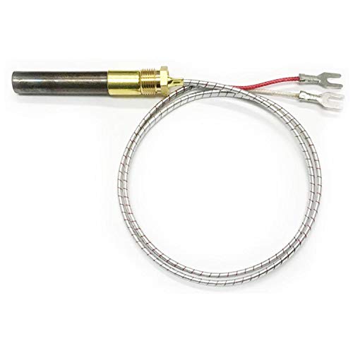
Thermopile
51827 is a thermopile used in the Majestic DV360 and DV580 direct vent gas fireplace series. This thermopile may also be used in select Monessen gas fireplaces.
Intermittent pilot ignition (IPI) fireplace
Intermittent pilot ignition (IPI) fireplaces are also referred to as electronic ignition fireplaces. As the name implies, the pilot light within the fireplace relights each time the fireplace turns on. Restarting the pilot flame each time eliminates the need for a continuous pilot. No longer having a need for a continuous pilot provides energy savings. The pilot assembly includes a pilot cap, igniter electrode and a flame sensor.
Gas supply tubing connects the pilot valve within the combination gas valve to the pilot cap. The igniter electrode lead connects to the “I” terminal of the IPI module. The flame sensor lead connects to the “S” terminal of the IPI module.
An intermittent pilot ignition fireplace requires power to operate. There are no thermocouples or thermopiles producing a voltage to control the gas valve. The power to the fireplace IPI module can come from two sources. The main source of power comes from the power adapter that plugs into a receptacle. An alternative source of power comes from a battery pack that connects to the IPI modules wiring harness. In the event of a power outage, the batteries within the battery pack, supply the IPI module with power to turn on the fireplace.
Intermittent Pilot Ignition
Compatible with Fireplace Brands – Astria, Coleman, Comfort Flame / Glow, Continental, Country Stoves, Dexen, FMI / Desa, Hearth & Home Technologies (HHT), Heatilator, Heat N Glo, IHP, Ironstrike, Lennox, Majestic, Insta Flame, Majco, Monessen, Napoleon, Outdoor Lifestyles, Quadra-Fire, RH Peterson, Real Fyre, SIT, Superior, Town & Country, Vanguard, Vexar.

Intermittent pilot ignition fireplace – sequence of operation
- Thermostat calls for heat, or ON/OFF switch is placed in the ON position
- High voltage spark generator circuit receives voltage and starts to create sparks
- Pilot valve receives voltage and opens
- Pilot assembly ignites
- IPI modules senses flame current
- Voltage removed from high voltage spark generator (no longer generates sparks)
- Main gas valve receives voltage and opens
- Main burner ignites
- When either the thermostat reaches its temperature setting or the ON/OFF switch turns OFF, both the pilot and main solenoids no longer receive voltage and close.
Wiring a 24VAC Nest thermostat to an intermittent pilot ignition fireplace
The wiring of the Nest thermostat, transformer and control relay coil is the exact same as the millivolt installation described above. The difference between the millivolt and IPI system is the wiring of the control relay contact. The black and red of the 18/2 thermostat wire connects terminals 2 and 4 of the control relay to either the IPI modules wiring harness or directly across the ON/OFF switch. When heat is called for, the Nest closes its “switch” and applies 24VAC to the coil of the control relay. The contact on the control relay will then close. The control relay contact then provides a path to supply voltage from the IPI module to open the pilot valve and start the spark generator.
Nest thermostat and intermittent pilot ignition (IPI) fireplace wiring diagram

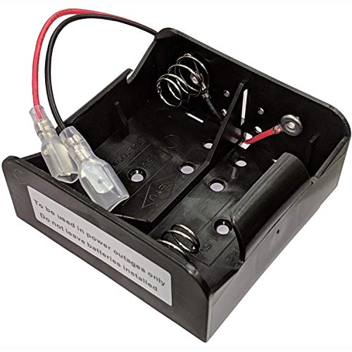
Battery Pack
Dexen battery pack for Dexen IPI electronic ignition system. Can operate the fireplace in the event of a power outage or if no electricity was run to the fireplace.
Parts required
- Nest Thermostat
- 120/24 VAC Transformer
- Thermostat Wire
- High Temperature Wire
- Control Relay
- Terminal Crimps & Crimping Tool
- Junction Box
- Cable Glands
Nest thermostat and Intermittent Pilot Ignition (IPI) fireplace wiring diagram using a plugin transformer

Parts required
- Nest Thermostat
- 120/24 VAC Plugin Transformer
- Thermostat Wire
- High Temperature Wire
- Control Relay
- Terminal Crimps & Crimping Tool
- Wire Nuts
How intermittent pilot ignition fireplaces create spark
Some intermittent pilot ignition fireplaces use inductive discharge to produce a high voltage spark across the pilot assembly’s igniter electrode. The simplified circuit below consists of a DC power source, two inductors, pulse width modulation controller, MOSFET switch and a capacitor. The DC source comes either from the IPI modules power adapter or from the battery pack. The two inductors are wound around a soft iron core connected as an autotransformer. The MOSFET switch electronically connects and disconnects the DC source from the primary inductor. The PWM controller gates the MOSFET, controlling when the switch is open or closed. The capacitor provides a path for current to flow when the MOSFET switch is open. This circuit enables the DC voltage from the power adapter or battery pack to produce a high voltage arc for ignition.
Note
Various IPI module manufacturers have proprietary circuit designs for this application. The following provides general knowledge of the circuit functionality. The IPI high voltage spark generator circuit diagram is simplified. For example, it does not show the electronics of the PWM or the MOSFET body diode, which prevents false gating of the MOSFET switch from transient voltages. The intent is not to dive into the electronics of the circuit, but rather to gain a basic understanding of how the circuit produces high voltage to create a spark.

Inductor basics
An inductor is simply a coil of wire designed to take advantage of the relationship between magnetism and electricity as current passes through it. When an electric current flows through an inductor, it produces a magnetic field around it. Conversely, exposing an inductor to a changing magnetic field generates an electric current through it.
The strength of the magnetic flux around the inductor varies depending on the amount of current flowing through the inductor. This magnetic flux stores energy in the form of kinetic motion of the electrons through the inductor. This energy storage results in an inductors ability to resist changes in current while trying to maintain current at a constant magnitude. When current through an inductor is increased or decreased, the inductor resists the change by inducing a voltage in the polarity necessary to oppose the change.
Increasing the current through an inductor induces a voltage drop, which opposes the direction of electron flow while the inductor absorbs the energy. The inductor acts as a load in the circuit when current increases. The polarity of the induced voltage across the inductor will be negative on the current entry side and positive on the current exit side.
Decreasing the current through an inductor induces a voltage drop, which aids the direction of electron flow while the inductor releases its stored energy. The inductor acts as a source in the circuit when current decreases. The polarity of the voltage across the inductor will be positive on the current entry side and negative on the current exit side.
Note
This explanation uses electron flow rather than conventional flow of current. In electron flow, current flows out of the negative terminal through the circuit and into the positive terminal of the DC source.
Induced voltage across an inductor
The amount of self-induced voltage developed is proportional to both the rate of change of the magnetic field and the number of turns within the inductor.
\small { V }_{ L }=N\cdot \frac { di }{ dt }
\small \begin{alignedat}{2}{ V }_{ L }&=induced\; voltage \\ N&=number\; of\; turns\; of\; the\; inductor \\ \frac { di }{ dt }&=current\; rate\; of\; change\; (amps/sec.)\end{alignedat}
When current flowing through the inductor is constant (di = 0), such as a steady state DC current from a battery, the induced voltage across the inductor will be zero. The DC current will flow at its maximum value, limited only by the resistance of the inductor, the ON resistance of the MOSFET switch as well as the discharge rate of the battery pack.
The amount of induced voltage across an inductor is directly proportional to the rate of current change flowing through it. The only difference between the effects of a decreasing current and an increasing current is the polarity of the induced voltage. The magnitude of the induced voltage will be the same for either an increasing or decreasing current as long as they have the same rate of change.
The more rapidly current is decreased; the more voltage will be produced by the inductor as it releases stored energy to try to keep the current constant. Likewise, the more rapidly current is increased; the more voltage will be produced by the inductor as it absorbs energy to try to keep the current constant.
High voltage spark generator circuit operation
When either the fireplace on/off switch or the Nest thermostat calls for heat, the IPI module will start the inductive discharge circuit. The PWM controller will start gating the MOSFET switch, controlling when the switch is open or closed. The MOSFET switch will close when the PWM controller supplies it with a voltage. Conversely, the MOSFET switch will open when no voltage is supplied by the PWM.
MOSFET switch closing
When the MOSFET switch closes, a current will flow from the battery, through the MOSFET, through the inductor and then back to the battery. The current flowing through the circuit does not rise rapidly to its maximum valve. The current is limited by the inductors self-induced emf as a result of the growth of magnetic flux. After five time constants, the current will reach its maximum value. Once the current reaches its maximum value, the inductance of the inductor has reduced to zero. At this point, the inductor resembles a short circuit. The current flows at its maximum value as determined by Ohm’s Law I = V / R, which is the battery voltage divided by the resistance value of the inductor.
MOSFET switch opening
When the MOSFET switch opens, the magnetic field encompassing both the primary and secondary inductors collapses rapidly. This rapid collapse induces a high voltage across the secondary inductor. Without the capacitor in the circuit, opening the MOSFET switch would instantaneously interrupt the current flowing through the primary inductor. This would theoretically induce an infinite voltage across the MOSFET, which would form an arc across the switch to dissipate the energy stored within the inductor. Installing a capacitor in parallel with the MOSFET allows primary current to flow thorough the capacitor when the MOSFET switch opens. The current flow through the capacitor decreases rapidly, however, it decreases at a controlled rate. The rate of change of the current flowing through the capacitor induces the desired high voltage across the secondary inductor. The voltage is high enough to produce a spark between the high voltage output terminal (igniter electrode) and ground.
Flame sensor
While the IPI module is generating sparks across the igniter electrode and pilot hood, the module also supplies a voltage to the pilot valve. The voltage opens the pilot valve allowing gas to flow. Once the gas reaches the pilot hood, the sparks ignite the fuel. When the IPI module detects a flame across the pilot cap and flame sensor, the IPI module stops the high voltage spark generator and applies a voltage to the main gas valve’s solenoid coil.
The IPI module detects a flame by applying a positive voltage from its “S” terminal to the tip of the flame sensor. The burning of gas results in a temperature of the flame that is high enough to ionize the atoms of the fuel. The high temperature results in the atoms aggressively bouncing into one another, which effectively frees electrons from the atom. Therefore, during combustion, both positively charged ions and free electrons coexist. The positively charged ions are drawn towards the pilot cap which is attached to ground, while the electrons are drawn towards the positively charged flame sensor. This ion and electron draw provides a path for a DC current to flow. The DC current flows from the ground connection of the pilot hood, through the flame sensor and back to the IPI module.
The amount of current flowing is in the microamp (µA) range; however, this small current is enough to prove to the IPI module that a flame exists.

Intermittent Pilot Ignition Pilot Assembly
The IPI Pilot Assembly utilizes state-of-the-art technology to provide quick and consistent ignition, ensuring reliable and hassle-free operation every time. With its high ignition success rate, you can enjoy instant warmth and ambiance.

Note
A flame sensor is merely a conductive rod with an insulator that prevents the rod from coming into contact with ground. A common misconception is that flame sensors behave similar to thermocouples and produce a voltage upon heating.
Related content
How to connect and setup a Nest thermostat to function as a humidistat
How to set up a Nest Thermostat with a whole house dehumidifier
Stop losing heat up your fireplace chimney