This article explains the differences between exhaust only, supply only, and balanced building ventilation. Additionally, this article has example calculations showing the differences between the ASHRAE 62.2-2010 and 2013 standard revision when sizing residential ventilation systems. Wiring diagrams show how to connect a ventilation controller to air handling units and bathroom exhaust fans. Ventilation sequence illustrations show the state of the equipment (on/off, open/close) to demonstrate how mechanical building ventilation operates. Lastly, this article explains the differences between heat recovery ventilators (HRV) and energy recovery ventilators (ERV). Wiring diagrams show how to interlock either an HRV or ERV with an air handler when they connect to existing building ductwork.
Purpose of mechanical building ventilation
Mechanical building ventilation provides better indoor air quality for the occupants. Indoor air quality improves by introducing fresh outdoor air while removing stale contaminated indoor air. The concentration of contaminants (toxins / pollutants) within indoor air can increase without proper ventilation. These contaminants can become odorous, cause sensory irritation, and pose a health risk. In addition to health concerns, proper selection of mechanical building ventilation can also protect the building structure.
Exhaust only mechanical ventilation performs better in cold climates whereas supply only ventilation performs better in hot, humid climates. Balanced mechanical building ventilation is optimal for all climates.
Ventilation requirements for older homes may not have needed mechanical building ventilation to maintain good indoor air quality. Many older homes rely on natural leaks through windows, doors and cracks/holes within the building envelope for ventilation requirements. The infiltration and exfiltration of air entering and exiting the building provide enough air exchanges per hour for good indoor air quality. Natural leaks may provide ventilation; however, natural leaks are inefficient and result in high energy costs.
Houses built to newer standards as well as older homes with building envelope upgrades/renovations have less natural ventilation. Better quality windows, doors, and attic sealing / insulation tighten the building envelope and increase the buildings energy efficiency. Homes with low natural air exchanges per hour require mechanical building ventilation to provide good indoor air quality.
How to calculate the required volume flow rate for mechanical ventilation
ASHRAE (American Society of Heating, Refrigerating and Air-Conditioning Engineers) is an organization that writes standards and guidelines for the HVAC industry. Their standards describe recommended practices in designing and installing HVAC equipment. The ASHRAE 62.2 Ventilation and Acceptable Indoor Air Quality in Residential Buildings standard details how to calculate ventilation rates.
The ASHRAE 62.2 total ventilation rate formulas below provide the buildings continuous ventilation rate requirements. Upon first glance, it appears that ASHRAE decided to increase the ventilation requirements in their 2013 revision of the standard. However, the 2013 and current revisions more accurately determine ventilation requirements. The standard first sets the total airflow equal to the whole house ventilation airflow target. The standard then subtracts the infiltration airflow credit (determined from a blower door test, climate zone, and house type) to size the ventilation fan. Whereas the 2010 revision assumes a natural infiltration air flow of 2 CFM per 100 square feet of floor area. Therefore, the 2010 standard may under ventilate air tight buildings with less than 2 CFM per 100 square foot leakage.
ASHRAE\; 62.2-2010
Q_{tot}\ =\ \left(0.01\ cfm/ft^2\ \cdot A_{floor}\right)+7.5\ cfm\cdot\ \left(N_{br}\ +1\right)

ASHRAE\; 62.2-2013
Q_{tot}\ =\ \left(0.03\ cfm/ft^2\ \cdot A_{floor}\right)+7.5\ cfm\cdot\ \left(N_{br}\ +1\right)
\small \begin{alignedat}{3}{Q}_{tot}&=total\; required \; ventilation\; rate\; (cfm) \\ {A}_{floor}&=dwelling\; unit\; floor\; area \; (ft^2) \\ {N}_{br}&=number\; of\; bedrooms\end{alignedat}
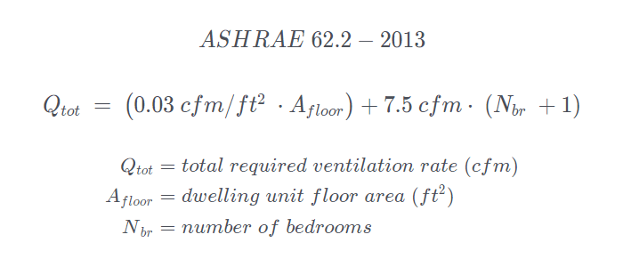
Afloor refers to the conditioned floor area within the building envelope, excluding garages. For example, if a house in a cold climate heats the basement, Afloor would include the basement floor area. The 2010 revision, then multiplies the Afloor by 1 CFM per 100 square feet and assumes 2 CFM per 100 square feet of air infiltration. The 2013 revision multiplies Afloor by 3 CFM per 100 square feet, and later subtracts the measured/calculated air infiltration credit. Additionally, the formulas add 7.5 CFM per number of bedrooms plus one. Plus one assumes that one of the bedrooms has two occupants.
ASHRAE 62.2-2013 calculation
For this example, we will use a house with the following specifications:
House type: bungalow with conditioned basement
House size: 1200 square feet
Number of bedrooms: 3
Location: Rochester
Height: 10.3 feet (distance from ground level to the highest ceiling)
Effective leakage area (ELA): 60 square inches (determined from blower door test)
Weather and shielding factor (wsf): 0.70 (from ASHRAE 62.2 Normative Appendix B)
Step 1
Calculate whole house ventilation airflow target (Qtot)
\small \begin{alignedat}{3}{ Q }_{tot}&=\ \left(0.03\ cfm/ft^2\ \cdot A_{floor}\right)+7.5\ cfm\cdot\ \left(N_{br}\ +1\right)\\Q_{tot}&=\ \left(0.03\ cfm/ft^2\ \cdot2400\ ft_{ }^2\right)+7.5\ cfm\cdot\ \left(3\ +1\right)\\Q_{tot}&=\ 102\ cfm\end{alignedat}

Step 2
Calculate normalized leakage (NL)
The next step of 2013 revision requires height correction to normalize leakage (NL). The requirement for height correction is because taller buildings are more subjected to stack effect, which results in greater infiltration and exfiltration. ASHRAE uses 8.2 feet as a reference height for a story. It does not matter if your house is a two story with 9 or 10 foot ceilings, you just need to measure the distance from the highest ceiling to ground level and divide by 8.2. Additionally, since the units for Afloor are in square feet, the units for the effective leakage area also need to change to square feet. To do this, simply divide the ELA from the blower door test by 144. 60/144 = 0.4167 square feet.
\small \begin{alignedat}{3}NL&=\frac{(1000\ \cdot ELA)}{Afloor}\cdot (H/Hr)^{0.4}\\NL&=\frac{(1000\ \cdot 0.4167)}{2400\ ft_{ }^2}\cdot(10.3/8.2)^{0.4}\\NL&=0.1902\end{alignedat}
Step 3
Calculate the effective annual infiltration rate (Qinf)
Next, calculate the effective annual infiltration rate (Qinf). The effective annual infiltration credit reduces the required mechanical ventilation for the house. The effective annual infiltration rate incorporates the height correction as well as a weather shielding factor. Refer to the Normative Appendix B section of the ASHRAE 62.2 standard for weather shielding factors for different locations throughout the United States and Canada. You simply select the wsf from the weather station closest to where you reside. The wsf applies throughout the entire year, even though the actual infiltration rate will vary at any given time.
\small \begin{alignedat}{3}Q_{\inf}&=\ \frac{(NL\cdot wsf\cdot A_{floor})}{7.3}\\Q_{\inf}&=\ \frac{(0.1902\cdot 0.70\cdot 2400\ ft_{ }^2)}{7.3}\\Q_{\inf}&=\ 43.8\ cfm\end{alignedat}
Step 4
Calculate the size of the fan required for adequate ventilation (Qfan)
The last step is to calculate the building mechanical ventilation requirements by simply subtracting the effective annual infiltration rate (Qinf) from the total required ventilation rate (Qtot) to receive (Qfan).
\small \begin{alignedat}{3}Q_{fan}&=Q_{tot}-Q_{inf}\\Q_{fan}&=102 \ cfm-43.8 \ cfm\\Q_{fan}&=\ 58.2\ cfm\end{alignedat}
ASHRAE 62.2-2010 calculation
\small \begin{alignedat}{3}{ Q }_{tot}&=\ \left(0.01\ cfm/ft^2\ \cdot A_{floor}\right)+7.5\ cfm\cdot\ \left(N_{br}\ +1\right)\\Q_{tot}&=\ \left(0.01\ cfm/ft^2\ \cdot2400\ ft_{ }^2\right)+7.5\ cfm\cdot\ \left(3\ +1\right)\\Q_{tot}&=\ 54\ cfm\end{alignedat}

Assumed infiltration of 2 CFM per 100 square feet equates to 48 CFM.
Note: The combined assumed infiltration and (Qtot) add up to the ASHRAE 62.2-2013 (Qtot) of 102CFM
In this example, the 2010 standard, sized the ventilation fan (supply/exhaust/combination) to 54 CFM while the 2013 standard sized the fan at 58.2 CFM. The size of the fans is close for this example, however, when the house is more air tight, the fan size between the two revisions of the standard will change considerably.
If we change the value of the effective leakage area from 60 to 20 square inches (more air tight), the ASHRAE 62.2-2013 would size the fan at 87.4 CFM while the 2010 standard would remain at 54 CFM. Implementing the 2010 standard for this more air tight house would under ventilate it.
Whole house exhaust ventilation
Exhaust only ventilation typically consists of a bathroom exhaust fan(s) and a controller that operates the fan in accordance with ASHRAE 62.2. The exhaust fan can operate either continuously at a slower speed or intermittently at a higher speed. The theory of operation is that the exhaust fan depressurizes the building while removing stale/contaminated indoor air. Depressurizing the building results in a negative household pressure. This allows fresh outdoor air to infiltrate the building through either intentional or small unintentional leaks within the building envelope.
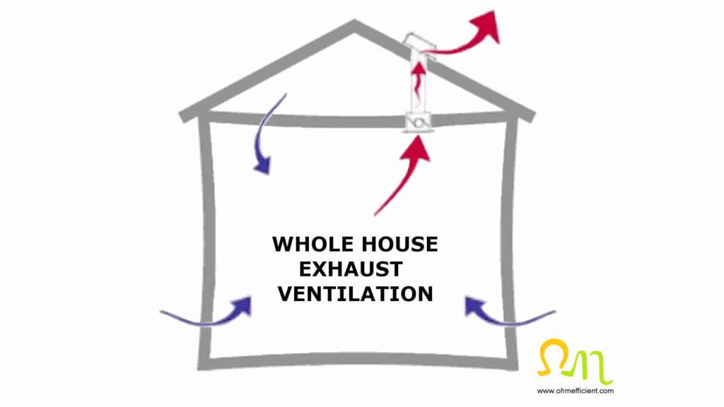
Fresh outdoor air replaces stale/contaminated indoor air that exhausts through the fan. If the building envelope is well sealed, fresh outdoor air will not replenish the exhaust air fast enough. When this occurs, it creates an imbalance and may result in an excessive negative household pressure. Excessive negative household pressures may cause spillage of carbon monoxide (back drafting) from fuel-burning appliances such as furnaces, water heaters and fireplaces. Back drafting is a condition where combustion byproducts come back into the house rather than exit through the chimney flue. This is a serious health concern and can be fatal if left undetected. Buildings with exhaust only ventilation should have carbon monoxide detectors placed throughout the building. Carbon monoxide detectors sound an alarm when they sense a certain amount of carbon monoxide over time. The alarm alerts the occupants of the carbon monoxide danger.
Whole house exhaust ventilation is more suited to cold climates where the relative humidity of the outdoor air is typically low. The use of whole house exhaust ventilation in warm, humid climates may draw moisture into the walls while humid air infiltrates the house. Mold within the wall cavities can develop as a result. Mold poses a risk to both health and the building structure.
Continuous exhaust ventilation
Energy efficient exhaust fans with ECM motors and optional variable speed control modules are ideal for exhaust ventilation. The variable speed fan replaces an existing single speed fan and allows for the speed of the fan to match the calculated ventilation rate. For continuous exhaust ventilation, wire the fan to operate 24 hours a day, 7 days a week. Multiple exhaust fans may be required depending on the square footage of the building.
Energy Efficient Exhaust Fan
This exhaust fan delivers quiet, powerful, and precise spot ventilation while removing moisture and pollution. An Energy Star rated exhaust fan that delivers powerful airflow without wasting energy.
Variable Speed Control Module
Multi-Speed bathroom fan: Select CFM to satisfy ASHRAE 62.2 continuous ventilation requirement.
Additionally, there is a requirement for the sound rating of the bathroom exhaust fan to be 1.0 sone or less for continuous exhaust ventilation. This sound rating prevents homeowners from turning the power off to the fan because of noise.
Intermittent exhaust ventilation
If the flow rate of the existing exhaust fan exceeds the calculated ventilation flow rate, an alternative solution would be to install an exhaust fan controller Replace either the fan on/off switch or timer with an exhaust fan controller. The controller will automatically turn the exhaust fan on and off to meet the required ventilation rate.
Example
Required ventilation rate = 58 cfm
Existing exhaust fan flow rate = 90 cfm
58 cfm x 60 minutes = 3,480 cubic feet per hour
3,480 cfh / 90 cfm = 38.7 minutes
Adjust the pre-set ventilation time to approximately 38.7 minutes to meet the required ventilation rate.
Exhaust Fan Controller
Smart Exhaust fan and light control replaces both fan and light switches for economical, simple and convenient operation. This exhaust fan and light combo features programmable delay and ventilation settings.
Whole house supply ventilation
Supply only ventilation typically ties into the return side of a central air system and is commonly referred to as either central fan integrated or ducted outdoor air ventilation. The outside air duct requires adequate negative pressure to draw air into the building. Therefore, the duct should connect within ten feet or less from the inlet of the air handler. The theory of operation is that fresh outdoor air enters the building when the motorized damper in the outdoor air duct is open and the central fan is running. The drawn in outdoor air pressurizes the building, which promotes exfiltration of stale/contaminated indoor air.
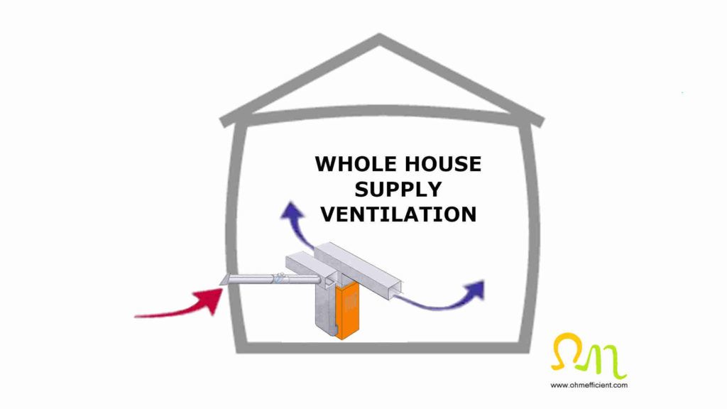
The benefit of supply only compared to exhaust only ventilation is that the fresh air comes from a known location. The fresh air also flows through the air handler filter and can be heated, cooled, or dehumidified. Additionally, supply ventilation provides a more even distribution of fresh air to all areas of the house.
The disadvantage of supply only ventilation is the higher energy usage operating the central fan/blower. The 2012 IECC (International Energy Conservation Code) requires air handlers incorporating supply air ventilation controls to have an ECM (Electronically Commutated Motor). If your air handler has a PSC (Permanent Split Capacitor) motor, replacement ECM motors are available to lower energy usage.
Whole house supply ventilation is more suited to warm climates where the relative humidity of the outdoor air is higher. The use of whole house supply ventilation in cold climates may result in exfiltration of humid indoor air through walls and roofs. When humid indoor air exits the building envelope, it will condense on cold surfaces which leads to mold and the deterioration of the building materials.
Controlling the air handler central fan for supply only ventilation
Operating supply air ventilation intermittently in conjunction with heating and cooling demands, typically results in under ventilation. Data from the Offermann (2009) Ventilation and indoor air quality in new homes report confirms that the ingress of outdoor air is limited to a small portion of the day. To ensure adequate delivery of outdoor air, the air handler central fan needs the ability to cycle on and off without a heating or cooling call. Typically, installing a ventilation controller accomplishes this. The outdoor airflow rate or the length of time for each cycle of the central fan can be set to provide sufficient outdoor air ventilation.
Supply only ventilation using a ventilation controller
Ventilation controllers integrate with the home’s HVAC system. The unit monitors and controls the HVAC central fan as well as opens and closes the ducted outdoor air damper. When the thermostat calls for either heating or cooling, the ventilation controller will open the fresh air damper to draw in fresh air. When there is no heating or cooling call, the controller may turn on the central fan and open the damper in order to meet the ventilation requirements for the hour.
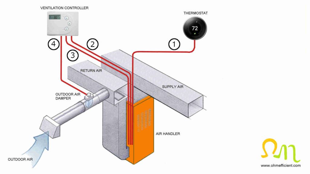
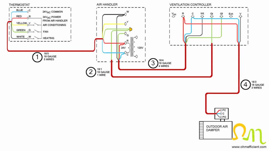
Parts and Materials Required
Ventilation Controller
Outdoor air damper
Hot wire anemometer
Thermostat wire
Wire nuts
Utility knife
Wire stripper
HVAC foil tape
Measure airflow during heating, cooling and fan only operation
The amount of airflow through the outdoor air duct will change depending on the speed of the central fan. Therefore, it is important to measure the amount of airflow during heating, cooling and fan only operation. The reason for this is that air conditioners typically require a flow rate of 400 CFM per ton. Flow rates for heating vary depending on the size and type of furnace:
Natural draft furnaces (70%) typically require 100 CFM per 10,000 BTU of rated BTU input
Induced draft furnaces (80%) typically require 130 CFM per 10,000 BTU of rated BTU input
Condensing furnaces (90%+) typically require 150 CFM per 10,000 BTU of rated BTU input
Example
Inducted draft furnace with a 60,000 BTU input that incorporates a 3-ton air conditioner.
The central fan would approximately operate at (60,000 BTU / 10,000 BTU) * 130 CFM = 780 CFM during a heating call. During a cooling call the central fan would operate at 400 CFM/ton * 3 ton = 1200 CFM.
How to measure airflow of ducted outdoor air
Measure the airflow through the outdoor air duct using a hot wire anemometer. Take a separate measurement of the airflow through the duct for each heating, cooling, and fan only operation. The hot wire anemometer measures the average air speed in the duct in feet per minute (FPM). Multiple the average air speed by the area of the duct in square feet to determine the airflow moving through the duct.
Example
If the fresh air duct connecting the outdoor intake hood to the return side of the air handler is a 6-inch round duct, the area of the duct would be 0.196 square feet.
\small \begin{alignedat}{4}A&=\pi r^2\\A&=\pi 3^2\\A&= 28.27\ square\ inches\\28.27 / 144&= 0.196\ square\ feet\end{alignedat}
If the hot wire anemometer measures the speed of the air at 510 feet per minute, then the airflow through the fresh air duct would equal: 510 FPM x 0.196 square feet = 100 CFM.
Watch the following video that details how to measure the CFM flowing within a duct.
Enter the airflow measurements from the hot wire anemometer into the ventilation controller’s air flow settings. The ventilation controller will then be able to calculate and control how much fresh air enters the house on an hourly basis.
Restrictions that lower airflow within a duct
Airflow within the outdoor duct decreases when the length of the duct or the number of bends increases. Additionally, decreasing the diameter of the duct as well as the type of duct (flex verses rigid), also decreases air flow. For this reason, as well as the varying speeds of the central fan, it is best to measure the air flow rather than assume.
Hot Wire Anemometer
Measure air velocity, temperature, and volume flow with just one instrument. Provides automatic calculations when combined with the smart probe app. The app erases the need for error prone manual calculations.
If we continue with the ASHRAE 62.2 example above, we would then set the ventilation controller’s code required constant air flow setting to Qfan or 58 CFM.
58 CFM x 60 minutes = 3,480 CFH (cubic feet per hour)
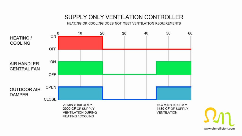
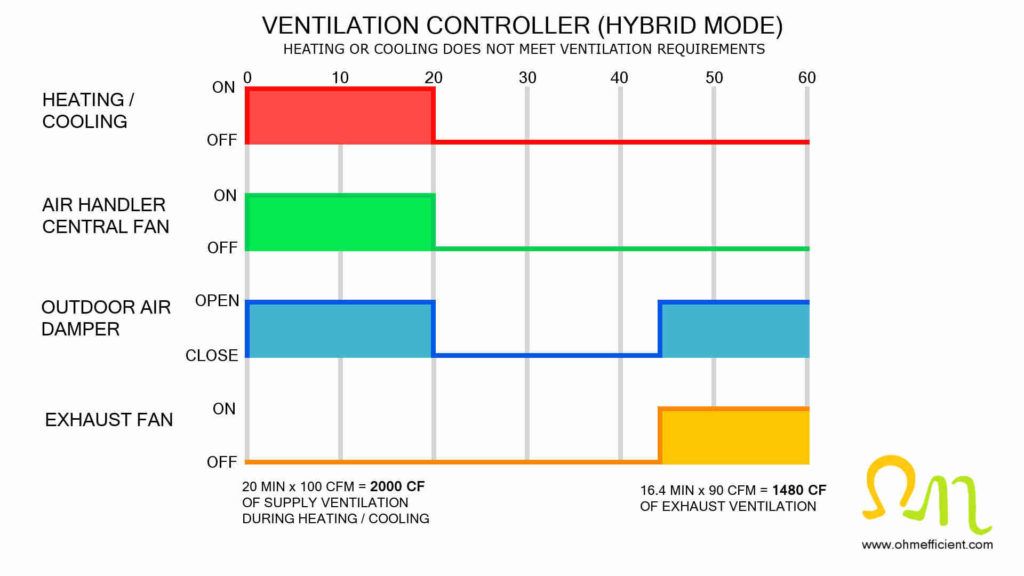
For this example, we will assume the measurements using the hot wire anemometer measured the air flow through the outdoor duct at 100 CFM for a cooling call and 90 CFM for a fan only call. If a cooling call operates the central fan for 20 minutes with the air flow through the outdoor duct at 100 CFM, the supply ventilation would add up to 20 minutes x 100 CFM = 2000 CF. This would not meet the total ventilation requirement for the hour of 3,480 CF. If there are no more cooling calls for the remainder of the hour, the ventilation controller will turn on the central fan and open the damper to meet the ventilation requirements.
With the air flow through the outdoor duct at 90 CFM during a fan only operation, the central fan would need to operate for an additional 16.4 minutes.
3,480 CF – 2,000 CF = 1,480CF
1,480 CF / 90 CFM = 16.4 minutes
The following ventilation sequence illustration breaks down the volume air flow for this example.
Balanced building ventilation
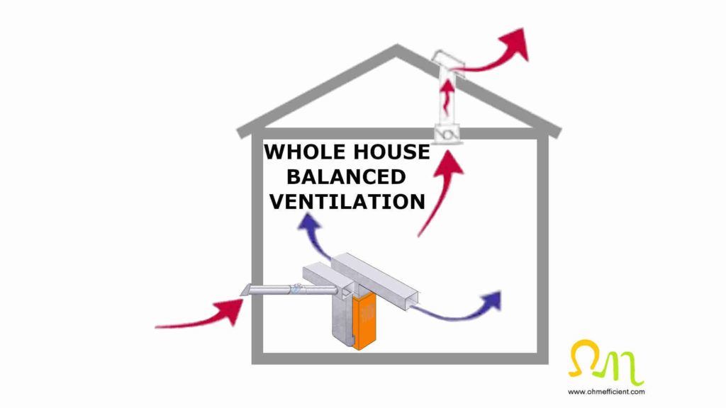
Balanced ventilation is a combination of supply and exhaust ventilation occurring simultaneously. To consider a system as balanced, the total supply airflow needs to be within 20% of the total exhaust airflow. Unlike exhaust only ventilation, which creates a negative household pressure or supply only ventilation, which creates a positive household pressure, balanced ventilation achieves close to atmospheric pressure. When the pressure of the interior of the building is close to the pressure on the exterior, the amount of air that exchanges through exfiltration or infiltration of the building envelope reduces. Reducing air infiltration or exfiltration reduces the chance of mold and improves indoor air quality.
Balanced ventilation using a ventilation controller
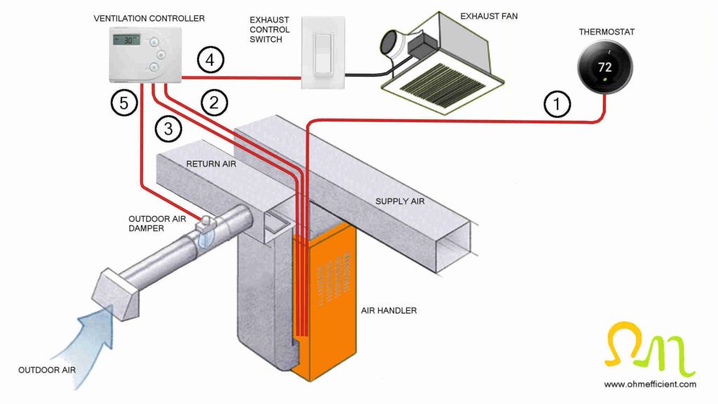
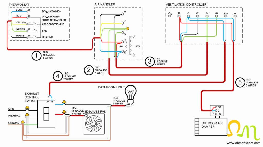
In addition to ventilation controllers controlling HVAC central fans and ducted outdoor dampers, ventilation controllers can also control exhaust fans. Replacing the existing exhaust fan switch/timer with an exhaust control switch allows the ventilation controller to operate the exhaust fan. An additional 2c#18 thermostat wire connects the ventilation controller’s Exh and C terminals to the exhaust control switches relay terminals. When the ventilation controller applies 24VAC across the exhaust switch internal relay coil, the internal 3-pole 120 volt switch toggles. Toggling this switch bypasses the exhaust fans manual on/off switch and applies 120 volts to the exhaust fan.
When the thermostat calls for either heating or cooling, the ventilation controller will turn on the exhaust fan and open the fresh air damper to draw in fresh air. When there is no heating or cooling call, the controller will turn on the central fan, exhaust fan as well as open the damper in order to meet the ventilation requirements for the hour.
Ventilation Controller
The SelectCycler system encompasses the WhisperGreen select ventilation fan or fan/light (sold separately), the system controller, motorized supply damper and FanConnect fan/light wall switch.
Parts and Materials Required
Ventilation controller
Outdoor air damper
Exhaust control switch
Energy efficient exhaust fan
Hot wire anemometer
Thermostat wire
Wire nuts
Utility knife
Wire stripper
HVAC foil tape
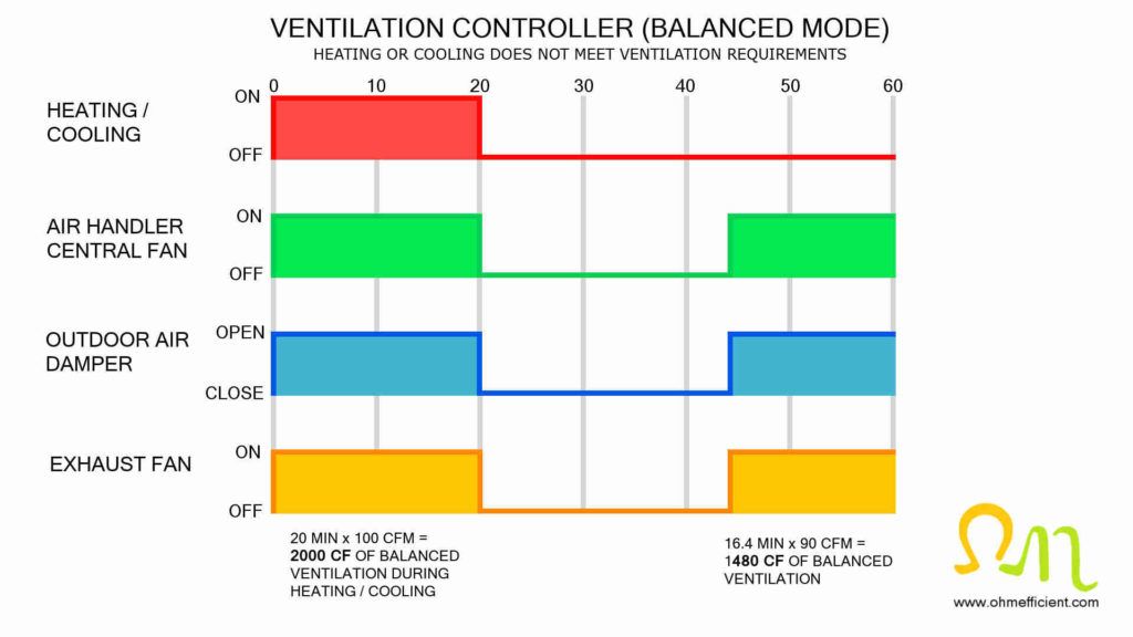
In balanced mode, the exhaust fan runs when the air handler central fan is on and the outdoor air damper is open. As mentioned previously, balanced ventilation requires the total supply air flow to be within 20% of the total exhaust air flow. Balancing the exhaust air flow to the supply airflow is easy when using energy efficient exhaust fans with variable speed control modules that automatically adjust the fan speed to ensure the desired CFM output.
How a bathroom exhaust fan turns on the furnace/air handler fan
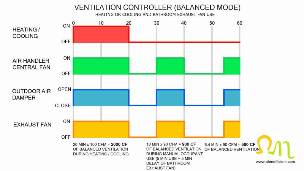
The ventilation controller and exhaust control switch incorporate two-way communication. This communication enables the ventilation controller to monitor normal exhaust fan use. In balanced mode, when someone uses the bathroom exhaust fan, the ventilation controller will turn on the air handler central fan. Therefore, normal exhaust fan use counts towards the total ventilation requirements for the hour. The exhaust control switch also incorporates an adjustable off-delay timer. This timer keeps the exhaust fan running for a set amount of time after turning off the switch.
How to set up a ventilation controller to operate in balanced mode
The default settings of a ventilation controller are to operate in hybrid mode. When left in hybrid mode, the ventilation controller opens the outdoor air damper during heating or cooling. This mode of building ventilation resembles the supply only configuration described above. If the combined total of heating or cooling cycles within an hour does not meet the building ventilation requirements; the ventilation controller would then open the outdoor air damper and turn on the exhaust fan. This mode of building ventilation resembles the exhaust only configuration descried previously.
To change the default setting of hybrid mode to balanced mode, simply navigate to the setting for the minutes of exhaust fan required and press the down button until SL displays on the screen.
Operating a ventilation controller in hybrid mode
Operating ventilation controllers in hybrid mode is an option for climates that have mild winters with average humidity levels during the summer. The benefit of operating a ventilation controller in hybrid mode is that it reduces the overall power consumption. A decrease in power consumption is a result of not operating the large air handler fan for the exhaust only ventilation period at the end of the hour. The savings are especially noticeable when air handlers incorporate older permanent split capacitor (PSC) motors, rather than newer, more energy efficient electronically commutated motors (ECM).
Heat recovery ventilator (HRV) / energy recovery ventilator (ERV)
Heat and energy recovery ventilators are balanced whole house ventilation systems that decrease energy demands on HVAC systems while improving indoor air quality. Exhaust only, supply only and the combined balanced ventilation systems improve indoor air quality, however, these systems do not recover any of the energy used conditioning the indoor air in the process. Exhaust only systems remove conditioned air from the building while cool air infiltrates the building. This results in the furnace running more often or for longer cycles to warm up the air within the building to the thermostat temperature setting. Likewise, supply only systems introduce warm air into the building while promoting exfiltration of conditioned air form the building. This results in the air conditioner running more often or for longer cycles to cool the air within the building to the desired temperature.
HRVs and ERVs exhaust stale indoor air and supply fresh outdoor air by exchanging the supply and exhaust air through their heat exchanger cores. During this air exchange, the supply and exhaust air do not mix as they have separate passages within the heat exchanger core. Exchanging these two air streams allows the conditioned exhaust air to either preheat or cool the fresh outdoor air entering the building.
During the heating season, the HRV/ERV transfers heat from the warm outgoing exhaust air to the cool incoming fresh air. This heat transfer preheats the incoming fresh air, which reduces the workload on the furnace. During the cooling season, the HRV/ERV transfers heat from the warm incoming fresh air to the cool outgoing exhaust air. This heat transfer pre-cools the incoming fresh air, which reduces the workload on the air conditioner.
Heat Recovery Ventilator
- Airflow up to 159 cfm @ 0.4″ PS serves 2 to 5 bedroom homes.
- External dry contacts for quick connection of remote controls.
- Washable electrostatic filters.
What is the difference between an HRV and ERV?
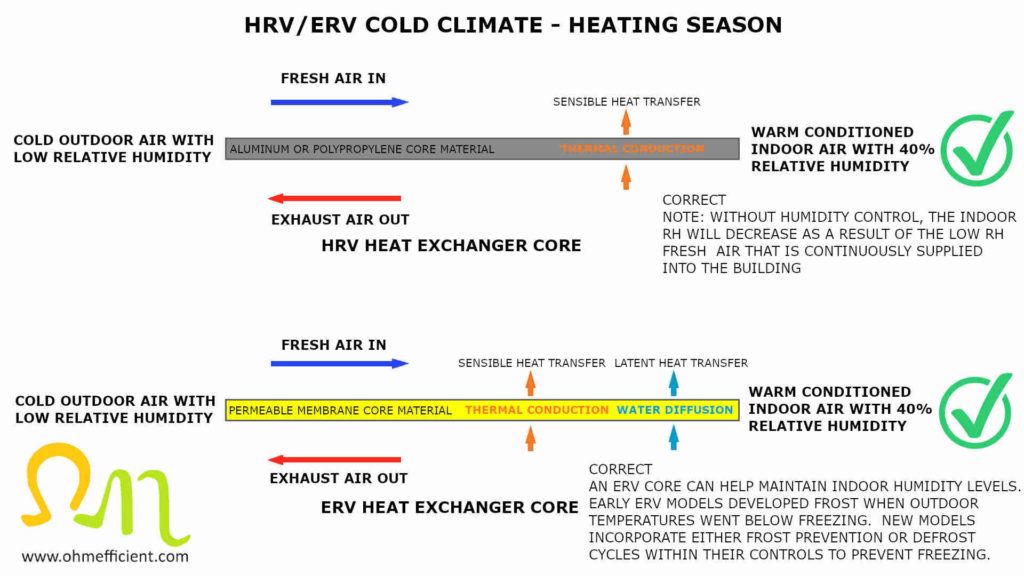
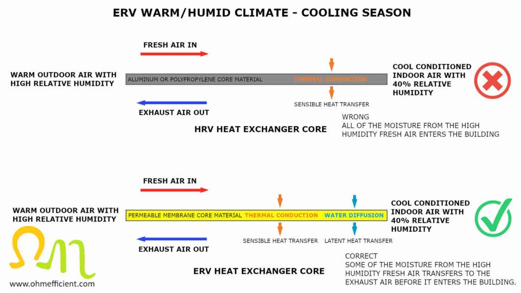
ERVs and HRVs are similar devices with the exception of the materials within the heat exchanger core. HRVs use either an aluminum or polypropylene core material, whereas ERVs use a permeable membrane core such as cellulose, polymer, or other synthetic materials. HRV cores only exchange sensible heat by transferring thermal energy between air streams. ERV cores exchange both sensible heat and latent heat and therefore transfer both temperature and moisture between air streams.
ERV cores passively transport moisture from the air stream with high relative humidity to the air stream with low relative humidity. Moisture from the high humidity air stream absorbs onto the surface of the ERV permeable membrane core. Then, simple passive diffusion allows the water molecules to cross the permeable membrane to the side with lower humidity. Diffusion refers to the movement of molecules from areas of high concentration to areas of lower concentration. Diffusion will continue to occur until there is an equal concentration on either side of the membrane. Moisture equilibrium will not occur while the ERV is in operation and air is continuously exchanging through the core. Note, the effectiveness of latent heat transfer decreases when the velocity of air exchanging through the core increases.
HRVs/ERVs in cold climates with low humidity
HRVs are commonly installed in cold climates, however, recent defrost control strategies now allow for ERVs to be used in cold climates as well. Traditionally, ERVs performed poorly in cold climates as the core was susceptible to freezing. When the core developed frost, the air exchange through the ERV became restricted and eventually blocked, rendering the ERV inoperable. Both HRVs and ERVs must therefore prevent the core from freezing. Periodically reducing ventilation or preheating the cold outdoor air accomplishes this.
HRVs/ERVs defrost cycles and frost prevention
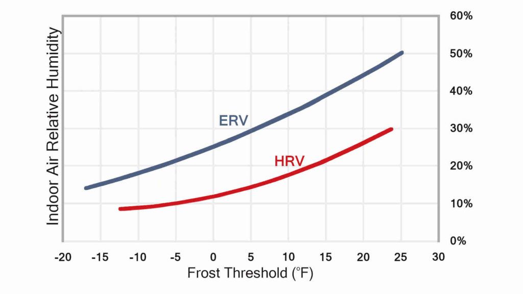
The frost threshold temperature at which frost starts to form in the exhaust airstream depends on the temperature and humidity of the exhaust air as well as the type and performance of the core itself. When warm exhaust air passes through the heat exchanger, the air cools as it transfers heat to the supply air. When the outdoor temperature is low enough, the exhaust air can cool down to its dew point temperature. At this point, the moisture within the exhaust air will condense and form water droplets on the heat exchanger. The condensation will start to freeze and create frost buildup when the temperature drops below the freezing point. This starts occurring at the point where the exhaust air exits the core, and the supply air enters the core.
To prevent ice buildup from blocking airstreams, both HRVs and ERVs can incorporate either a defrost cycle or frost prevention strategy. Defrost cycles allow frost to build up, followed by controls to melt the frost and drain the water from the system. Whereas frost prevention as the name implies, prevents frost buildup from occurring.
ERVs are capable of transferring moisture from the exhaust air to the supply air. This transfer reduces the frost threshold temperature compared to that of an HRV. Referring to the graph below: If the indoor air relative humidity is at 30%, frost would start to form within the HRV heat exchanger at 23oF (-5oC). Likewise, with an indoor air relative humidity of 30%, frost would only start to form within an ERV heat exchanger at 4oF (-20oC). The lower frost threshold temperature reduces how often an ERV is required to operate a defrost cycle. Reducing defrost cycles can help ensure that ASHRAE 62.2 continuous ventilation rates are met.
Recirculation defrost cycle
The recirculation defrost cycle strategy temporarily routes stale indoor air back through the heat exchanger core to defrost ice formation. During the recirculation defrost cycle, the exhaust fan shuts down, both the outdoor and exhaust air dampers close, and the recirculation air damper opens. This allows the supply fan to pull stale indoor air through the heat exchanger core. The stale indoor air then flows through the open recirculation air damper and back through the heat exchanger core. The absence of cold outdoor air during this cycle allows for the frost to melt and drain from the system.
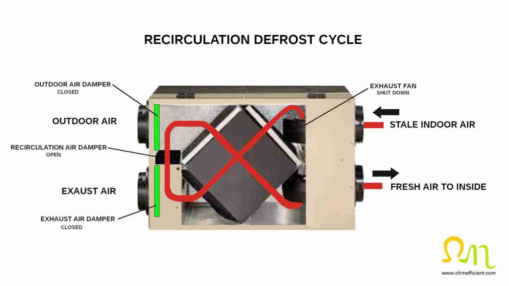
The downside of this defrost strategy is that ventilation is interrupted throughout the duration of the cycle. Additionally, the amount of time that the defrost and ventilation cycles operate change with outdoor temperature. Lower outdoor temperatures increase the defrost cycle time as well as decrease the ventilation cycle time before starting another defrost cycle.
Note
Interrupting ventilation during a defrost cycle may not meet the ASHRAE 62.2 continuous ventilation rates previously discussed.
Exhaust only defrost cycle
The exhaust-only defrost cycle strategy temporarily stops cold outdoor air from entering the HRV/ERV heat exchanger. This strategy provides a simple and cost-effective way to defrost ice formation. During the exhaust only defrost cycle, the supply fan shuts down and the outdoor air damper closes. The absence of cold outdoor air during this cycle allows for the frost to melt and drain from the system.
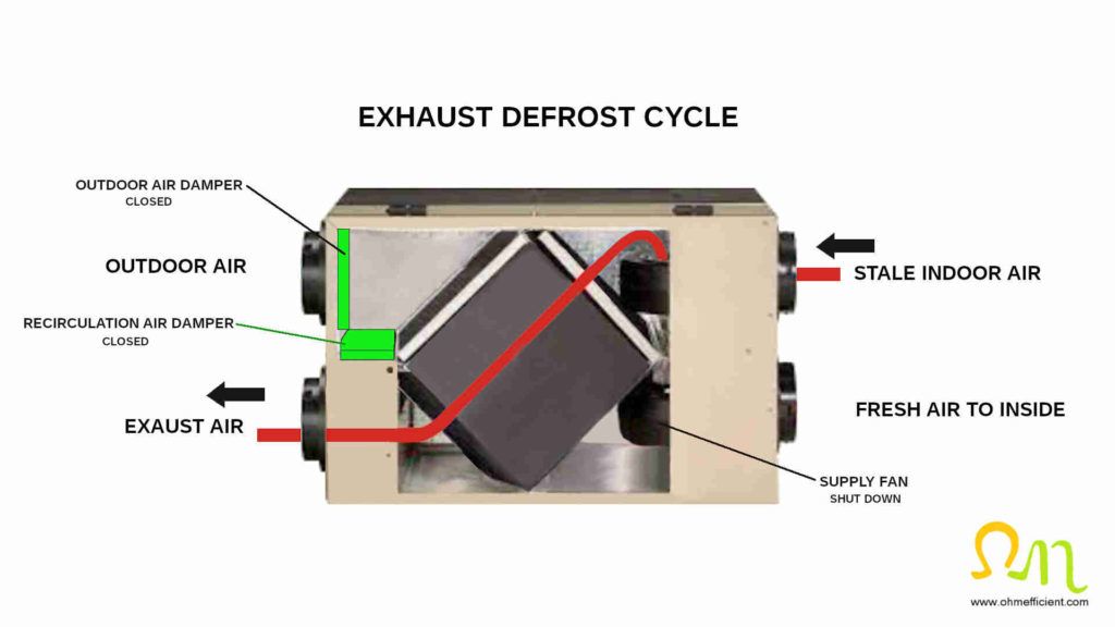
The downside of this strategy is that the ventilation system transitions from a balanced system to an exhaust only system. During this time the system creates a negative household pressure, which results in infiltration and possible back drafting of combustible appliances.
Preheat coil frost prevention
Frost prevention using a preheat coil increases the temperature of the outdoor air entering the heat exchanger. The preheat coil is sized so that the temperature of the fresh outdoor air entering the HRV/ERV is kept above the frost threshold temperature. Pulse modulated heaters can maintain the temperature above the frost threshold, while reducing electrical consumption when outdoor conditions require less pre-heating. There is no risk of frost since the outdoor air temperature entering the HRV/ERV is always kept above the frost threshold temperature.
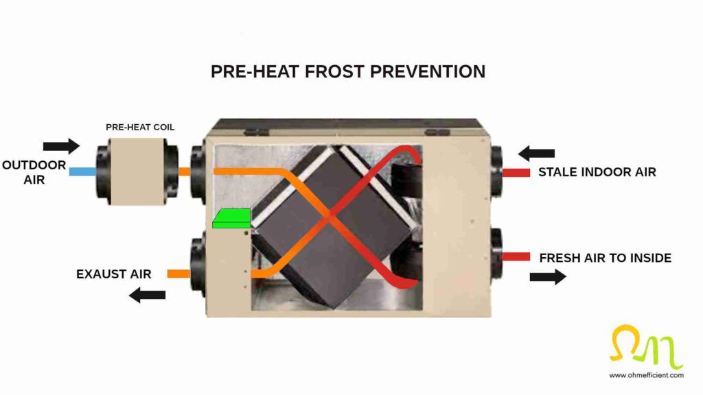
The advantage of frost prevention is that it provides the ability to continuously ventilate without interruption from defrost cycles. This allows for ASHRAE 62.2 continuous ventilation rates and improved indoor air quality as a result.
The downside of this frost prevention strategy is that the preheat coil consumes more electricity, maintaining the outdoor air temperature above the frost threshold temperature. Additionally, the HRV/ERV is less efficient as energy recovery is reduced. Energy recovery is reduced because the difference in temperature between the preheated outside air and the exhaust air has reduced.
ERVs in warm climates with high humidity
Only ERVs should be used in warm, humid climates. The ERVs ability to transfer latent heat reduces the amount of moisture that enters the building. The percentage of water vapor in air varies with temperature, from 0.01% at -42oC (-44oF) to 4.24% at 30oC (86oF). Water vapor has approximately two times more specific heat capacity than air. Therefore, less energy is required to lower the temperature of air with lower levels of humidity. ERVs therefore reduce the load placed on your air conditioner in warm, humid climates which saves energy and money.
HRV efficiency
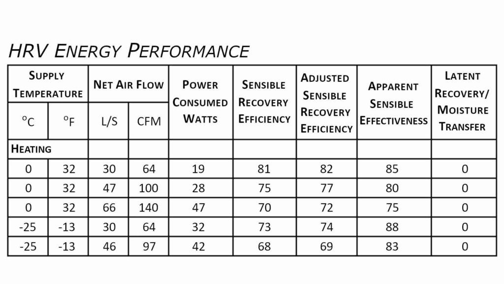
The efficiency rating of an HRV/ERV is measured using SRE (Sensible Recovery Efficiency), ASRE (Adjusted Sensible Recovery Efficiency), and ASEF (Apparent Sensible Effectiveness). Additionally, TRE (Total Recovery Efficiency) and ATRE (Adjusted Total Recovery Efficiency) are ratings for ERVs that measure both sensible and latent heat recovery efficiency. Higher ratings equate to more efficient heat/energy transfer.
Sensible Recovery Efficiency (SRE): solely refers to the sensible heat recovered by the supply airstream from the exhaust airstream. SRE is measured as a percentage of the total potential sensible energy that could be recovered. This value is best used to compare product efficiencies.
Adjusted Sensile Recovery Efficiency (ASRE): refers to the sensible heat recovered by the supply airstream from the exhaust airstream plus the heat gain from the fan motors. This value is used to calculate building heat load within energy modeling softwares.
Apparent Sensible Effectiveness (ASEF): is an efficiency rating often provided by equipment manufacturers. This rating has the highest efficiency percentage as it additionally includes heat transfer from fan motors, case heat gain, air leakage, airflow imbalance as well as heat transfer from defrost cycles. HRVs/ERVs are not certified using the ASEF rating, as comparing models based on ASEF alone can be misleading. For example, an inefficient fan motor that generates more heat than an energy efficient fan motor would increase the ASEF for a product that consumes more electricity.
ERV efficiency
Total Recovery Efficiency (TRE): solely refers to the sensible and latent heat recovered by the supply airstream from the exhaust airstream of an ERV. TRE is measured as a percentage of the total potential energy that could be recovered. This value is best used to compare cooling season product efficiencies.
Adjusted Total Recovery Efficiency (ATRE): refers to the sensible and latent heat recovered by the supply airstream from the exhaust airstream plus the heat gain from the fan motors. This value is used to calculate building heat load within energy modeling softwares.
Latent Recovery / Moisture Transfer (LRMT): refers to the ERVs ability to transfer moisture between airstreams. LRMT is rated on a scale of 0 to 1. 0 indicates that no moisture was transferred between airstreams. A value of 1 would indicate a complete transfer of moisture between airstreams. This value helps compare humidification or dehumidification performance between products.
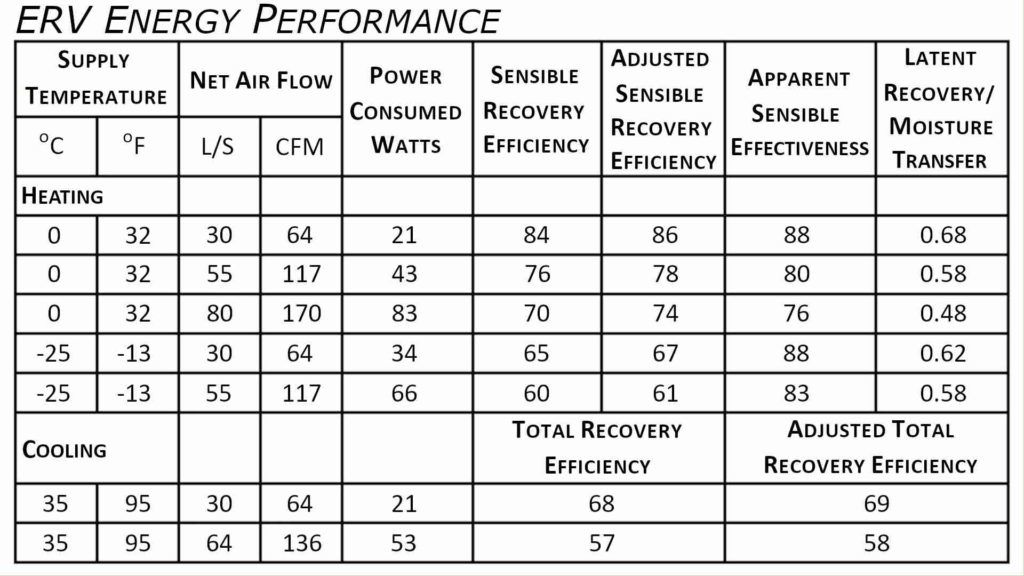
HRV’s and ERV’s are certified for airflow performance, as well as for effectiveness of transferring heat/energy, for easy comparison. The HVI (Home Ventilating Institute) certifies HRV/ERV efficiencies. Refer to the HVI list of certified products to compare HRV/ERV efficiency and airflow performance.
Direct ducted HRV/ERV systems
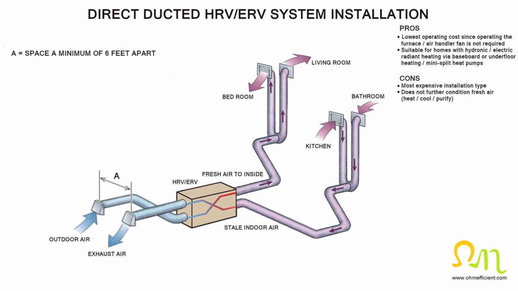
Direct-ducted HRV/ERV systems are typically found in new homes that do not have traditional forced-air systems. Buildings with mini-split heat pumps or hydronic/electric radiant underfloor/baseboard heating are examples where direct ducted installations are found. It is less common to find this type of installation in older homes that have undergone energy efficient renovations. The reason why it is less common is because installing the dedicated ductwork is difficult and cost prohibitive.
Dedicated HRV/ERV systems typically supply fresh air to bedrooms, living and dining rooms and basements. Removal of stale air typically comes from high moisture areas such as kitchens, bathrooms, and laundry rooms. One benefit of this installation is that there is no need for an interlock between the HRV/ERV and furnace/air handler. This reduces the overall operating costs of the ventilation system as less electricity is consumed.
Forced air return duct HRV/ERV systems
Installing an HRV/ERV to a forced air return duct is commonly found in energy efficient renovations in older buildings. Additionally, this installation type is found in new buildings with forced-air systems to reduce initial ventilation installation costs.
Air throughout the house returns to the furnace/air handler via the return air duct. This air is considered stale, from which a portion of it exhausts outdoors via the HRV/ERV. The stale air that is pulled from the forced air return duct is balanced through the exchange of fresh air from the HRV/ERV connection to the return air duct downstream. The fresh air from the HRV/ERV enters the furnace/air handler and is distributed throughout the house. Due to the difference in pressure between the HRV/ERV and the furnace/air handler return duct, the HRV/ERVs airflow must be balanced on site following the manufacturers installation procedure.
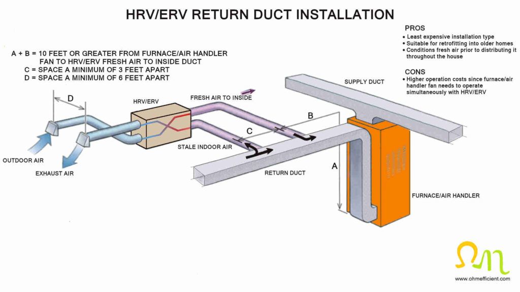
HRV/ERV return duct installations require an interlock between the furnace/air handler fan and the HRV/ERV. This interlock forces the furnace/air handler fan to run simultaneously during HRV/ERV operation. This ensures proper distribution of fresh air throughout the house. In addition to air distribution, interlocking also prevents the HRV/ERV airflow from short circuiting. Airflow short circuiting refers to air from the “fresh air to inside” connection being pulled back out the “stale indoor air” connection.
Furnaces/air handlers with high-efficiency ECM motors are recommended for use with this installation configuration. This is because ECM motors can run at a low speed with low noise and use less electricity.
How to interlock an HRV/ERV with a forced air system
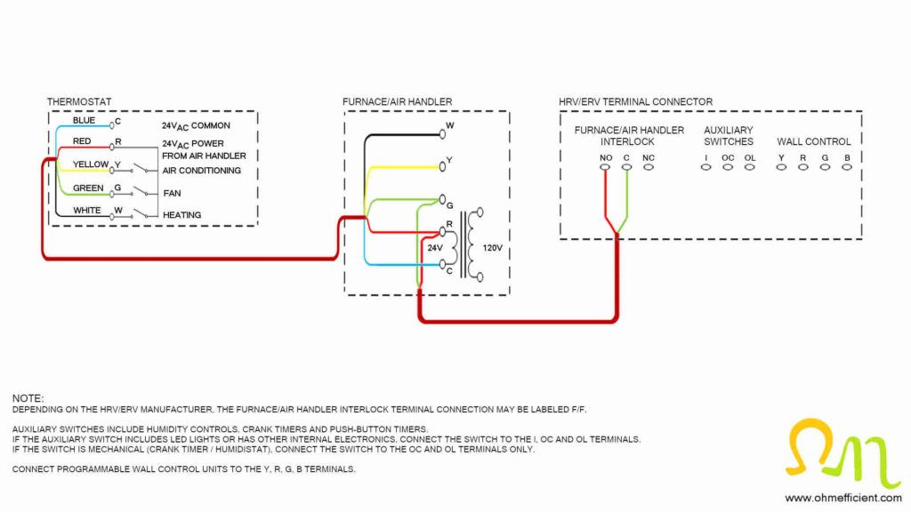
To interlock the HRV/ERV and furnace/air handler for simultaneous operation, use a 2c#18 thermostat wire. Connect the HRV/ERV NO and C (F and F) terminals to the furnace/air handler G and R terminals. When the HRV/ERV wall control or an auxiliary switch calls for ventilation, the HRV/ERV NO and C (F/F) contact closes. This contact then applies 24VAC from the furnace/air handler transformer to terminal G. When terminal G receives 24VAC, the furnace/air handler fan starts.
Balancing HRV/ERV supply and exhaust
The supply and exhaust airflow through an HRV/ERV needs to be balanced to achieve designed heat/energy recovery. Airflows should be balanced during the initial installation of the equipment. Additionally, the airflows should be measured and adjusted when required annually.
Upon initial installation, imbalance typically occurs because of the difference in the amount of ductwork between the supply and exhaust airstreams. Other sources that can create an imbalance include dirty filters, clogged intake or exhaust hoods and malfunctioning components such as dampers and fans.
Manometer
Use the UEi EM201B to measure gas supply and draft pressures in residential or
light commercial properties. The differential mode provides a convenient method to measure pressure drops.
To balance an HRV/ERV, you first need to close all exterior windows and doors and turn off all exhaust fans. Exhaust fans include bathroom, range hood and clothes dryer. For direct ducted HRV/ERV installations, the furnace/air handler should also be turned off. For return duct installations, the fan within the furnace/air handler needs to be running.
HRV/ERV balancing procedure
Set the HRV/ERV to operate at high speed. Wait 10 minutes before balancing if the outdoor temperature is below 32oF (0oC) to ensure the unit is not in a defrost cycle.
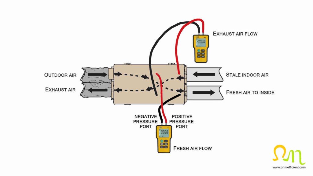
Connect the digital manometer positive and negative pressure port tubing to the exhaust airflow pressure tabs. These pressure tabs are usually located on the access door used to remove the heat exchanger core for maintenance. Be sure to remove the pressure tab cap before connecting the tubing. If the digital manometer pressure is reading a negative pressure, reverse the tubing connections. Refer to the pressure/airflow conversion chart label attached to the HRV/ERV. Find the exhaust pressure on the chart and make note of the equivalent airflow in CFM.
Move the digital manometer tubing from the exhaust air pressure tabs to the supply air pressure tabs. Make sure to reinsert the exhaust pressure tab caps. Refer to the pressure/airflow conversion chart again and find the supply pressure and the equivalent airflow in CFM.
Depending on the total required ventilation rate (Qtot) of the house, either the exhaust airflow, supply airflow or both may need to be adjusted. How to adjust the airflow depends on the manufacturer and the technology used within their product. Some HRVs/ERVs use adjustable dampers that restrict airflow, while others use variable speed ECM motors to adjust airflow. Either adjust dampers or vary the speed control of the fan motor until both the supply and exhaust airflow are within 10% of each other.
Once complete, write the pressure and equivalent airflow on a label and attach it to the HRV/ERV for future reference.

